DIAMOND Storage Ring Optical and X-ray Diagnostics
180 likes | 301 Views
This document presents an in-depth introduction to the optical and X-ray diagnostics employed in the DIAMOND storage ring. It covers essential tools such as streak cameras and multi-channel analyzers for visible diagnostics, along with X-ray pinhole cameras to assess beam characteristics. The technical specifications of the 3 GeV storage ring and the booster are highlighted, detailing both transverse and longitudinal imaging, energy spread analysis, and purity measurements. Key metrics and results illustrate the performance of the electron beam diagnostics, essential for optimizing synchrotron radiation output.

DIAMOND Storage Ring Optical and X-ray Diagnostics
E N D
Presentation Transcript
DIAMOND Storage Ring Optical and X-ray Diagnostics
I. Introduction to DIAMOND II. Visible diagnostics lines - Streak camera - Multi-channel analyser III. X-ray diagnostics lines - X-ray pinhole camera
Storage ring 3 GeV (comm. Jan. 2006) Booster 0.1 – 3 GeV Ø 178.3 m LINAC (comm. May 2005) 100 MeV 48 potential beamlines 25 March 2004
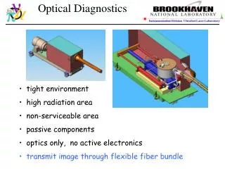
The optical Diagnostics 1 - Imaging transverse and longitudinal beam 2 - Analysis of the image beam characteristics 2 X-ray pinhole cameras: emittance, energy spread Transverse axis: 1 visible CCD camera: watching the beam Streak camera: bunch long. distribution, analysis of long. instabilities Longitudinal axis: Collimator + multi-channel analyser: purity of the buckets Photodiode + oscilloscope and / or spectrum analyser
Location Two bending magnets BM 1, ID 1 + hutch (prefab.) for the optical lab. (40 m2) streak camera CCD, Bunch purity, etc.
Dipole 1 (ID 1) X-ray pinhole camera Dipole 2 (BM 1): X-ray pinhole camera Streak camera CCD camera Visible light optical hutch Collimator + Multi-channel analyser Photodiode + fast oscilloscope / spectrum analyser
Tp Tt T Beam characteristics at the source points in BM 1 and ID 1 Time domain Pulse length st = 10 ps relative energy spread se= 0.001 Time inter pulse, Tp = 2 ns Pulse train duration, Tt = 1.248 ms Revolution period, T= 1.872 ms Transverse plane sy emittance e = 2.7 nm rad sx sx = 50 mm sy = 25 mm
Visible S.R. from Dipole 2 O.D. S S.C. Power meter 1.5 m CCD Computer collimator PMT + MCA 3 m S: remote controlled shutter PMT : Photo multiplier tube O.D. : graduated optical density MCA : Multi-channel analyser S.C. : Streak camera
Streak camera Electron bunch longitudinal distribution, f Bunch length ( <f2> ) Evolution Bunch centroid ( <f> ) Broad band impedance: f ≡ f (Zn /n)
Streak camera - fast sweep at 250 MHz sweep range: 175 - 1200 ps - slow sweep sweep range: 20 ns - 70 ms - ‘firewire’ CCD camera software solution for acquisition > 70 ms
Bunch purity measurement Statistical distribution of electrons in the ring SR PC N. dens. Coll. PMT MCA 1015 Ph / s 4.2 106 Ph / s = 8 Ph / turn Number of channels > 15 bits (32768) Resolution: 32 ps / channel Memory > 20 bits / channel (106)
X-ray pinhole camera G. Rehm – Acquisition of diagnostic screen and synchrotron radiation images using IEEE 1394 digital cameras - Poster - 1 W 10 mW Cu 0.8 ° Firewire CCD Al (3 mm) Pinhole (25 mm2) Lens screen (outside vacuum) 45 W d = 4 m D = 8 m Magnification 2
Photon counting: On the screen 1010 photons / s @ > 15 keV Image Size (3 s) 300 150 mm2 On the CCD Pixel size: 10 10 mm2 Energy conversion rate: 10 % Number of photons / pixel: ≈ 20 Ph/ ms@ 1 mA ≈ 10 103 Ph / ms@ 500 mA
Size of the photon beam in Dipole 1 and 2 vs. relative energy spread b, a, g, h, h’, and e known D = 8 m d = 4 m
Accuracy of the measurement • Computed accuracy: • Generate set of distributions of Twiss parameters • Generate a set of photon beam sizes on the screen, assuming se0 and e0 • Fit the sizes with the nominal Twiss parameters • Find a distribution set of emittances and relative energy spread • retrieve the centre and the standard deviation of the distributions
Conclusion • A set of optical measurements to diagnose the quality of the • DIAMOND electron beam has been designed. 6-dimensional phase space: Streak camera images: bunch length, bunch centroid, impedance X-ray pinhole camera: transverse sizes, emittance, energy spread Electron bunch train quality: Multi-channel analyser with 32 ps resolution, 106 dynamical resolution