Download
1 / 21
210 likes | 359 Views
Application of Signal and Noise Theory to Digital VLSI Testing. Vishwani D. Agrawal Auburn University, Dept. of Elec. & Comp. Engg. Auburn, AL 36849, U.S.A. Nitin Yogi NVIDIA Corporation, Santa Clara, CA 95050. 20 th April 2010 28 th IEEE VLSI Test Symposium Santa Cruz, CA.

E N D
Application of Signal and Noise Theory to Digital VLSI Testing Vishwani D. Agrawal Auburn University, Dept. of Elec. & Comp. Engg. Auburn, AL 36849, U.S.A. Nitin Yogi NVIDIA Corporation, Santa Clara, CA 95050 20th April 2010 28th IEEE VLSI Test Symposium Santa Cruz, CA
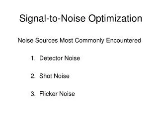
Introduction • Propose an information and noise analysis method for digital signals using Hadamard transform. • Analysis identifies information (spectrally structured) and noise (random) contents of the signal in relative measures. • The analysis is useful in a variety of applications like test generation, BIST, test compression, etc. • We illustrate its application to test generation. VTS'10, Santa Cruz, CA
Test Vectors and Bit-streams Circuit Under Test (CUT) Outputs Input J Input 3 Input 5 Input 1 Input 4 Input 2 A digital binary bit-stream signal vector Vector 1 → Vector 2 → Vector 3 → Vector 4 → Vector 5 → Vector 6 → Vector 7 → Vector 8 → Time in clocks Nitin Yogi - Doctoral Defense
Hadamard Transform • Hadamard transform transforms a digital signal from time domain to frequency-related domain. • Uses Walsh functions, which are a complete orthogonal set of basis functions that can represent any arbitrary bit-stream. • Can be used for binary signals by using the representation {0,1} -> {-1,1} w0 w1 w2 w3 Walsh functions (order 3) w4 H(8)= w5 w6 w7 time Example of Hadamard matrix of order 8 VTS'10, Santa Cruz, CA
Hadamard transformation Forward transformation (time domain to spectral domain): where: X Time domain digital signal vector of stream of N bits H(N) Hadamard transform matrix of order N S Hadamard transform (Walsh spectrum) of X Reverse transformation (spectral domain to time domain): VTS'10, Santa Cruz, CA
Properties of Hadamard Transform • Orthogonality and symmetry • Energy conservation where: • H(N)Hadamard transform matrix of order N • X Binary bit-stream vector in time domain • SHadamard transform in spectral domain (Walsh spectrum) VTS'10, Santa Cruz, CA
Energy Analysis • Total energy in a {-1,+1} binary signal of length N clocks in time domain: • Total energy in spectrum: VTS'10, Santa Cruz, CA
Analysis of random binary bit-streams • Values of spectral components of random binary bit-streams can be approximated as Gaussian distribution • Mean (µ) = 0 • Standard deviation (σ) Equal to N(by energy conservation) Equal to 0(since mean = 0) • where: • Sr(j)jth spectral component of a random binary bit-stream of length N • Square of the mean of Sr(j) VTS'10, Santa Cruz, CA
Spectral coefficients of random bit-stream • 500 samples of random binary bit-streams of length 64 were generated • Distribution of values of spectral components analyzed • Mean = 0.0035 ≈ 0 • Standard deviation = 1.000425 ≈ 1 Spectral components below a magnitude of 2σ or 3σ can be treated as noise components 3σ (99.73%) 2σ (95.45%) 1σ (68.27%) VTS'10, Santa Cruz, CA
Generating spectral bit-streams • Perform Hadamard transform on binary bit-stream. • Filter out noise-like spectral components having magnitudes less than a spectral threshold(Energy conservation of the transfom transfers the energy of filtered components to noise). • Perform reverse Hadamard transform to obtain time-domain values in the range (-1,+1) for bits in the bit-stream. • Time-domain values are normalized to range (0,1) and used as probabilities of logic 1 in new random bit-streams. VTS'10, Santa Cruz, CA
Generating spectral bit-streams Example {0,1} binary bit-stream {-1,+1} binary bit stream (X) Hadamard transform (S) Hadamard Matrix H(3) {0,1} converted to {-1,+1} = VTS'10, Santa Cruz, CA
Example of generating spectral bit-streams Unfiltered spectral component Spectral threshold = 2 σ = 2 Hadamard transform (S) of 8-bit binary bit-stream 0’s are filtered spectral coefficients Probabilities for generating bit-streams Normalization for probabilities Time-domain Reverse transformation VTS'10, Santa Cruz, CA
Generated spectral bit-streams Randomly generated bit-streams from probabilities Original {0,1} binary bit-stream Unfiltered spectral component Probabilities for generating bit-stream Generated bit-streams exhibit similar correlation with the unfiltered spectral component as the original bit-stream. Few bits changed by noise are shown in red. 1 bit difference between original bit-stream & unfiltered spectral component VTS'10, Santa Cruz, CA
Application of analysis • Application of spectral information analysis: • Test generation, BIST, Test data compression, etc. • Illustration of effectiveness of analysis using test generation • Test vectors generated for RTL faults (PIOs & flip-flops) • Generate spectral vectors & fault grade on circuit • Compare with random, weighted random & randomly perturbed vectors • Analysis applied to ISCAS’89 benchmark circuits • s1488, s5378 & s38417 VTS'10, Santa Cruz, CA
Spectral coefficients & power analysis for s1488 • 32 vectors were generated to detect RTL faults (PIOs & FFs) & analyzed using H(32) VTS'10, Santa Cruz, CA
Gate level coverage for s1488 VTS'10, Santa Cruz, CA
Gate level coverage for s5378 VTS'10, Santa Cruz, CA
Gate level coverage for for s38417 VTS'10, Santa Cruz, CA
Conclusion • Proposed an information analysis framework to distinguish noise from signal content • Illustrated effectiveness of method for the application of test generation • The method can easily be extended to other applications like BIST and test compression. See, • N. Yogi and V. D. Agrawal, “BIST/Test-Compressor Design using Combinational Test Spectrum,” Proc. 13th IEEE VLSI Design & Test Symp. (VDAT), July 2009, pp. 443-454. • N. Yogi and V. D. Agrawal, “Sequential Circuit BIST Synthesis using Spectrum and Noise from ATPG Patterns” Proc. 17th IEEE Asian Test Symp. (ATS), Nov 2008, pp. 69-74. • There is potential for further applications. VTS'10, Santa Cruz, CA
Thank you Questions please? VTS'10, Santa Cruz, CA
Test generation comparison with commercial tool Test generation: N. Yogi and V. D. Agrawal, “Spectral RTL Test Generation for Gate-Level Stuck-at Faults,” Proc. 15th IEEE Asian Test Symp. (ATS), Nov 2006, pp. 83-88. * Sun Ultra 5, 256MB RAM BIST: • N. Yogi and V. D. Agrawal, “Sequential Circuit BIST Synthesis using Spectrum and Noise from ATPG Patterns,” Proc. 17th IEEE Asian Test Symp. (ATS), Nov 2008, pp. 69-74. VTS'10, Santa Cruz, CA