Download
1 / 20
200 likes | 287 Views
Review of Correlator Developments in North America B. Carlson. Outline. BEE2/CASPER prototype ATA Haystack/MIT ALMA EVLA CARMA. BEE2/CASPER ( UC Berkeley/Caltech; Werthimer ). 8 antenna, dual pol’n, full stokes (or 16 antenna single pol). 150 MHz/pol’n, 256 channels per product.

E N D
Review of Correlator Developments in North AmericaB. Carlson
Outline • BEE2/CASPER prototype • ATA • Haystack/MIT • ALMA • EVLA • CARMA
BEE2/CASPER (UC Berkeley/Caltech; Werthimer) • 8 antenna, dual pol’n, full stokes (or 16 antenna single pol). • 150 MHz/pol’n, 256 channels per product. • Built of general purpose FPGAs and libraries; scalable in Nant, Nchan, BW. • FX: 8-bit ADC, 18-bit polyphase filter, 4-bit CMAC in X-part, 48-bit accumulators. High spectral dynamic range. • <~5% sensitivity loss; 8-bit FIR in F.B., 4-bit re-quant. • Used at Greenbank for the PAPER re-ionization experiment.
ATA (NSF/SETI Institute; Urry) • Expandable up to 352 antennas. 8-bit ADC, 100 MHz / poln, all 4 pol’n products, 1024 channels/baseline. • 1024 channel polyphase filter bank. Each F card can filter both pol’n from 4 antennas. 4-bit truncation after F, then onto corner-turner. • Used cPCI form factors and standard dual backplane cPCI chassis. The corner turner ‘C’ card plugs into the back of each slot. • Point-to-point routing from the corner-turner card to the X card via the point-to-point wiring card. Requires 1 flat ribbon cable per antenna to go from F to X. • 100 MHz, 352 antenna system requires 4 racks, each one containing 4 cPCI chassis. Plan is to build 2 independent 100 MHz systems, for a total of 8 racks. • ~4 different cards + cPCI backplanes, power supplies.
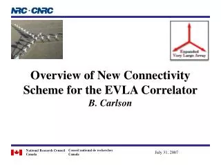
Corner turner card Back of filter bank chassis
Haystack/MIT (Cappallo) • Geodetic VLBI (NASA): interfacing Mk5B disk systems to the Mk4 correlator. VSI standard. “SU” mode allows replacement of station units. • Correlator FOV shaping (NSF): study to develop and test techniques to limit correlator FOV; SKA. Limit post-processing when using large arrays of small antennas. • Correlator for the Mileura Widefield Array (NSF, CSIRO, et al) (Bunton). • 125k baseline correlator for the 500 antenna MWA LFA. 32 MHz, 4 pol’n products. FX, polyphase filterbanks, using DSP multipliers in Xilinx Virtex 4 FPGAs.
ALMA (NRAO; Greenburg) • 64 antennas. • 8 BBs, 2 GHz/BB per antenna; 16 GHz/antenna. • 3-bit ADC. • 1024 leads, 1024 lags at 2 GHz BW. (1024 chans/baseline?) • 32k leads, 32k lags at 62.5 MHz BW (at all bandwidths with TFB card). (32k chans/baseline?) • 1 msec delay tracking range. • All pol’n products. • Digital filter for bandwidth selection below 2 GHz. • 16 msec integration time cross, 1 msec auto. • 2 Gbyte/sec total output data rate capacity. • Phased array outputs. • Pulsar gating. • 13 cards/backplanes/power cards of various sorts.
EVLA (NRC, NRAO; Carlson) • 16 GHz/antenna. 32-antenna system…expandable…can tradeoff BW/#ants/#beams; VLBI ready. • 3/8-bit ADC, 4/7-bit re-quantization and correlation…more bits/less BW possible. • All digital +/-1/32 sample delay tracking; 0.26 sec delay range. • 16k channels/baseline wideband; up to 4 Mchannels/baseline narrowband with “recirculation”. • Up to 144 tunable digital filters per antenna. • ~60 dB spectral dynamic range. • “WIDAR” technique (hybrid). • Station Board: FPGAs for filter banks…multi-stage filters in Xilinx Virtex-IV SX35s. RT Interference blanking. VSI I/Fs • Baseline Board: 8x8 array of 2048 c-lag, 4-bit corr chip; 0.13 um; FPGAs: high-speed LTA, 1-10 Gbps Ethernet out. • High-speed pulsar phase binning; 2000 bins/product, min ~15 usec. • Phased output…1 GHz…expandable to full BW. • 2 big cards, 8 total PCBs of various sorts. 32-station: 24 racks. • Hot-swap, no single-point failures.
CARMA (OVRO/Caltech; Hawkins) • 15 antennas, 500 MHz (and down to 2 MHz). • 8-bit 1 Gs/s initial sampling, with digital filtering (includes sub-sample delay) capability. • 2-bit (deleted inner products) or 4-bit correlation. • 101 channels/baseline (500 MHz, 2-bit); 26 channels/baseline (500 MHz, 4-bit). Up to 401 channels/baseline @ 2 MHz. • Lag/ XF architecture with phase switching. • ~40 dB spectral dynamic range. • cPCI card/chassis with Altera Stratix II FPGAs (15W ea, 125 MHz), on-board CPU (Freescale 8349E Power QUICC II Pro) + memory, RT Linux. • One card design is both the digitizer/station card and the correlator card. Outsourcing schem cap, PAR, thermal, mfg. • 16 baselines per board. 4 racks(?)