Download
1 / 18
190 likes | 285 Views
Learn a standardized approach to diagnose electronic equipment issues and save time, money, and prevent downtime. Follow the six-step method for systematic troubleshooting. Enhance your skills with detailed system elaboration and circuit localization tips.

E N D
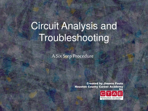
Circuit Analysis and Troubleshooting A Six Step Procedure Created by Jimmie Fouts Houston County Career Academyfor
Essential Question • How can a standardized approach toward electronic equipment troubleshooting save many hours of equipment downtime and costly repairs?
A Six Step Procedure? • A standardized approach toward electronic troubleshooting and maintenance: • Prevents equipment “down time” • Saves time needed for repairs when required • Ensures operation to design standards • Saves money!
The SIX-STEP Procedure • Use of a six-step procedure will provide a logical approach to trouble analysis • The six-step procedure is as follows: • 1. Symptom recognition • 2. Symptom elaboration • 3. Listing of probable faulty functions • 4. Localizing the faulty function • 5. Localizing trouble to the circuit • 6. Failure analysis
1. Symptom Recognition • Determine if the equipment is functioning as designed. Is it normal or abnormal? • A trouble symptom is a sign or indicator of a malfunction • Use your senses of sight and hearing! Indicator lights, speakers, meters…smoke! • Look for degraded performance as well; degraded performance often leads to equipment failure • Know your equipment!
2. System Elaboration • Observe any “built-in” indicators for more detailed information on symptoms • Obtain a detailed description of any trouble symptoms • Similar symptoms can be caused by similar faults! • Check front panel switches and control settings • What fault is probably causing the specific symptoms in question?
Symptom elaboration requires an evaluation of all observed displays • Indications must be evaluated in relation to each other as well as the overall operation • Record information observed! For example: How did each control affect an associated meter or other indicator? • “Think” about the information before jumping to a conclusion!
3. List Probable Faulty Functions • Many equipments have more than one functional area or unit • “Where can the trouble logically be in order to produce the information gathered?” • For example: Your computer contains RAM, a motherboard, a processor, a power supply, a hard drive….. What functional area might be at fault? • Dividing the equipment into functional areas can save numerous trouble shooting steps
Functional Block Diagram! • Useful in the isolation of a fault! • Example: • Microphone: Converts sound energy into electrical energy at an audio frequency • Modulator: Amplifies the audio signal and sends it to the transmitter to change the carrier signal to be modified • Transmitter: Provides an amplified radio frequency (RF) signal to the antenna assembly • Antenna Assembly: Converts the electrical RF signal into an electromagnetic energy for transmission. It also receives electromagnetic energy and converts it into an RF signal for the Receiver Unit • Receiver Unit: Converts received RF signal into sound • Power Supply: Converts alternating (AC) voltage into suitable direct current (DC) for operation of the various units
4. Localizing the Faulty Function • Up to this point, no test equipment has been required; only the equipment controls and indicators have been used • You can probably make a decision on where the most probable area for the malfunction is • Knowledge, skill, and proper test equipment should now be used to isolate the faulty functional area
Consider the Following Factors! • Which functional unit will give the best information for eliminating other units? • Which test points are more easily accessible? • What past experience and history do you have concerning similar faults with this particular equipment? • Are there other external units that may prevent proper operation of this unit?
5. Localizing Trouble to the Circuit • More extensive troubleshooting is now required within the identified faulty unit • Isolate circuits within the faulty unit • Circuits and stages in circuit groups perform basic sub-function vital tasks • Look for improper voltages, improper waveforms, obvious component overheating • Isolate the defective circuit group!
6. Failure Analysis • Steps 1 and 2 were used to recognize, verify, and obtain descriptive information • Step 3 allowed you to make a logical selection of the logical faulty unit • Step 4 provided for simple input-output tests and localized the faulty functions • Step 5 localized the fault to the circuit within the faulty unit • Step 6 will involve the actual replacement or repair of faulty circuit components
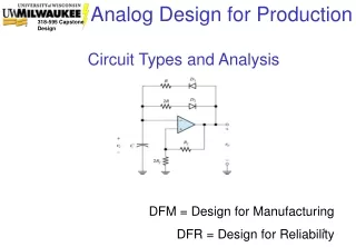
Schematic Diagrams • Illustrate the detailed circuit arrangement of electronic parts that make up complete circuits • Parts are represented symbolically • Show what is inside the “blocks” of the block diagram • Often provide voltage and resistance charts • Actual faults can generally be traced to one or several individual parts – resistors, capacitor, transistors, etc.
Complete, Degraded, Intermittent • Complete or abnormal performance of a component usually results in equipment failure • “Degraded” performance is the result of equipment not operating as designed or to design specifications • An intermittent part malfunction refers to something that stops operating, then begins operating again
Isolation of Faulty Parts • Observe the output signal of the circuit group • Voltage, duration, waveform shape • Conduct a visual inspection of parts and leads in the circuit • Look for burned parts or defective connections • Perform resistance checks • Ensure ALL power sources are OFF to the unit • Don’t expect identical readings to the schematic. Tolerances of as much as 20% may be acceptable. • Some equipments may require specialized test equipment. Refer to the Maintenance Manual.
BE AWARE of MULTIPLE FAULTS! • Often active components fail because of other components within the circuit • Common causes of failures may include: • Biasing resistor value changes causing a defective transistor • Defective capacitors failing to block DC current • Power surges from a power supply may cause burn-out of system components • Excessive current usage causing defective fuses • Intermittent faults that cause random failure
Return of Equipment to Operation • After replacing the faulty part or components always recheck equipment for proper operation! • Record your actions….they may be needed for future repairs!