CIRCUIT ANALYSIS
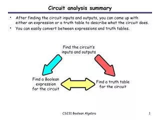
This guide provides a comprehensive overview of Ohm's Law, circuit analysis, and electrical measurements. It covers fundamental concepts such as current, voltage, and resistance, explaining how they relate through the equation V = IR. It discusses the types of electrical circuits (series, parallel, and combination), and the application of Kirchhoff’s Laws for circuit analysis. The importance of using ammeters and voltmeters for measurements is highlighted, ensuring a solid foundation for students and professionals in electronics and electrical engineering.


CIRCUIT ANALYSIS
E N D
Presentation Transcript
OHM’S LAW CIRCUIT ANALYSIS ENGR. VIKRAM KUMAR B.E (ELECTRONICS) M.E (ELECTRONICS SYSTEM ENGG:) MUET JAMSHORO
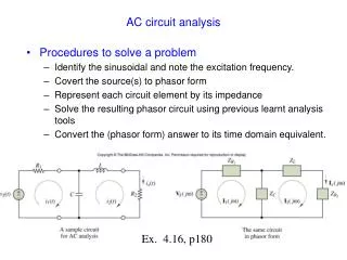
Electrical Meters Ammeters measure current in amperes and are always wired in series in the circuit. AMPS Voltmeters measure potential in volts and are always wired in parallel in the circuit. volts
- + A V Electrical Symbols battery junction wiring terminal voltmeter AC generator ammeter Variable resistance resistance Variable capacitor capacitor
THE MOST BASIC ELECTRICAL CIRCUIT LOAD (RESISTANCE) [ENERGY OUT] ELECTRONS INTO LOAD ELECTRONS OUT OF LOAD CONDUCTOR CONDUCTOR ELECTRONS OUT OF SOURCE ELECTRON PUMP (SOURCE VOLTAGE) [ENERGY IN] ELECTRONS BACK TO SOURCE HIGHER ENERGY ELECTRONS LOWER ENERGY ELECTRONS
Potential In volts (joules / coul) Current In amperes (coul / second) Resistance In ohms (volts / amp) Ohm's Law V = I R Drop across a resistance Current passing Through the resistor
volts Electrons have More Energy Electrons have Less Energy Potential Rise Across a Power Source current current Battery Electrons get An energy boost
volts Electrons have Less Energy Electrons have More Energy Potential Drop Across a Resistor current Resistor Energy is lost In the resistor
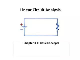
4.2 - Ohm’s Law • Every conversion of energy from one form to another can be related to this equation. • In electric circuits the effect we are trying to establish is the flow of charge, or current. The potential difference, or voltage between two points is the cause (“pressure”), and resistance is the opposition encountered.
Ohm’s Law • Simple analogy: Water in a hose • Electrons in a copper wire are analogous to water in a hose. • Consider the pressure valve as the applied voltage and the size of the hose as the source of resistance. • The absence of pressure in the hose, or voltage across the wire will result in a system without motion or reaction. • A small diameter hose will limit the rate at which water will flow, just as a small diameter copper wire limits the flow of electrons.
Ohm’s Law Where: I = current (amperes, A) E = voltage (volts, V) R = resistance (ohms, )
A2 R2 A1 R3 R1 There are three generally types of electrical circuits: • Series circuits in which the current created by the voltage • source passes through each circuit component in succession. Arrows show Current path Through each component
R1 A2 R2 A3 R3 R4 A4 (2) Parallel circuits in which the current created by the voltage source branches with some passing through one component and while the rest of the current passes through other components. A1 Arrows show Current path Through each component Junction or Branching points
P A R A L L E L A1 R1 A2 R2 A3 R3 R4 A4 SERIES (3) Series Parallel circuits or combination circuits which contain series segments and parallel segments. Arrows show Current path Through each component
All electrical circuit analysis requires the use of two fundamental laws called Kirchhoff’s Laws
Junction point Kirchhoff's Circuit Laws FIRST LAW All current entering a junction point must equal all current leaving that junction point Current Leaving ( I3 ) Current Leaving ( I2 ) I1 =I2 +I3 Current Entering ( I1 )
Kirchhoff's Circuit Laws SECOND LAW Around any complete loop, the sum of the voltage rises must equal the sum of voltage drops Resistance 1 (voltage drop 1) Resistance 2 (voltage drop 2) Resistance 3 (voltage drop 3) Current flow Complete loop Battery (voltage rise) - + V(Battery) = V1 + V2 + V3
V2 Loop #2 Current Loops A2 R2 Loop #3 Complete current Paths in a circuit V1 A1 R1 Loop #1 • Kirchhoff’s Laws • Around a loop • V rises = V drops A loop is a completed Path for current flow EMF - + At Battery
When using Kirchhoff’s laws we apply the principles of conventional current flow. When current leaves the positive (+) terminal of a voltage source and enters the negative (-) terminal a voltage rise occurs across the source. If the current enters the positive and exits the negative a of a voltage source a voltage drop occurs across the source. When tracing a current loop, if the assumed direction of the current and the loop direction are the same, a voltage drop occurs across a resistance. If the assumed direction of the current and the loop direction are opposite, a voltage rise occurs across the the resistance.
Battery ( 6 volts) - + When using Kirchhoff’s laws we apply the principles of conventional current flow. When current leaves the positive (+) terminal of a voltage source and enters the negative (-) terminal a voltage rise occurs across the source. If the current enters the positive and exits the negative a of a voltage source a voltage drop occurs across the source. V = - 6 v Current flow Current flow V = + 6 v
resistor When tracing a current loop, if the assumed direction of the current and the loop direction are the same, a voltage drop occurs across a resistance. If the assumed direction of the current and the loop direction are opposite, a voltage rise occurs across the the resistance. V = - 6 v A voltage drop Loop direction Assumed Current flow Loop direction Assumed Current flow V = + 6 v A voltage rise