Download

1 / 4
40 likes | 234 Views
Present Manual Control System for Alcator C-Mod MSE Shutter (Schematic). frame supporting wheels. clamps to feedthroughs. Rotatable shutter (in vacuum). conflats. rod. wire cable. Linear feedthrough A. stiff tube. Linear feedthrough B. wire cable. handle.

E N D
Present Manual Control System for Alcator C-Mod MSE Shutter (Schematic) frame supporting wheels clamps to feedthroughs Rotatable shutter (in vacuum) conflats rod wire cable Linear feedthrough A stiff tube Linear feedthrough B wire cable handle • We want to rotate the shutter into one of three positions: • Position #1: linear feedthrough A almost fully “in” & feedthrough B almost fully “out”. • Position #2: linear feedthrough B almost fully “out” & feedthrough B almost fully “in”. • Position #3: linear feedthroughs A and B in an intermediate position. • To ensure that all cables remain in a state of tension, the back ends of the two linear feedthroughs are • connected with a restraining cable that loops around two wheels supported on fixed axles. • Presently, we manually push and pull to position the shutter in the desired position. • To ensure that the rotatable shutter is positioned properly, we need an accuracy of about 2 millimeters on the • position of each linear feedthrough. • The system of wire cables that controls the movement of the rotatable shutter is pretty “stiff”. I estimate that about • 5-10 pounds of force are required to move them. • If we pull too far in one direction, we will probably break the connection between the internal wire cable and the • shutter. So we to provide for stops that limit the push-pull of both linear feedthroughs. restraining cable
Optical slot switches (TBD) 14CCF series Berg Cable chain 0.1475” pitch Linear feedthrough A 2.5” Linear feedthrough B 14LP5S-52 Berg chain sprocket Sprocket diameter = 2.4563” OD = 2.536”, 3/8” bore (pin or clamp hubs assemble on request) Need to figure out means of connection to linear feedthrough Proposal #1 for Remote MSE Shutter Control
Remote MSE Shutter Control Optical slot switches (TBD) 14CCF series Berg Cable chain 0.1475” pitch Linear feedthrough A 2.5” Linear feedthrough B 1.0-1.75” diameter Berg chain sprocket Berg chain sprocket (Size to match existing wheels) Need to figure out means of connection to linear feedthrough Need belt tensioner?
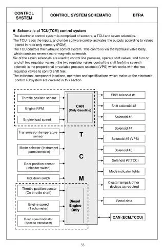
Schematic of Stepper Motor Control System Chain sprocket shaft Stepper motor Supporting Frame Torque limiters (2) Are these needed? optical switch outputs motor drive electronics ? power supply PLC