RFID SECURITY ACCESS CONTROL SYSTEM
RFID SECURITY ACCESS CONTROL SYSTEM. Submitted by:. contents. Project overview Block diagram Power supply Microcontroller RFID Relay BC 547 LCD Software requirements Schematic & Working of the project Advantages Applications Future scope Conclusion. Project overview.

RFID SECURITY ACCESS CONTROL SYSTEM
E N D
Presentation Transcript
RFID SECURITY ACCESS CONTROL SYSTEM Submitted by:
contents • Project overview • Block diagram • Power supply • Microcontroller • RFID • Relay • BC 547 • LCD • Software requirements • Schematic & Working of the project • Advantages • Applications • Future scope • Conclusion
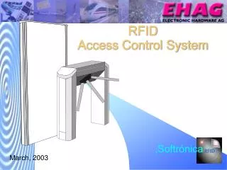
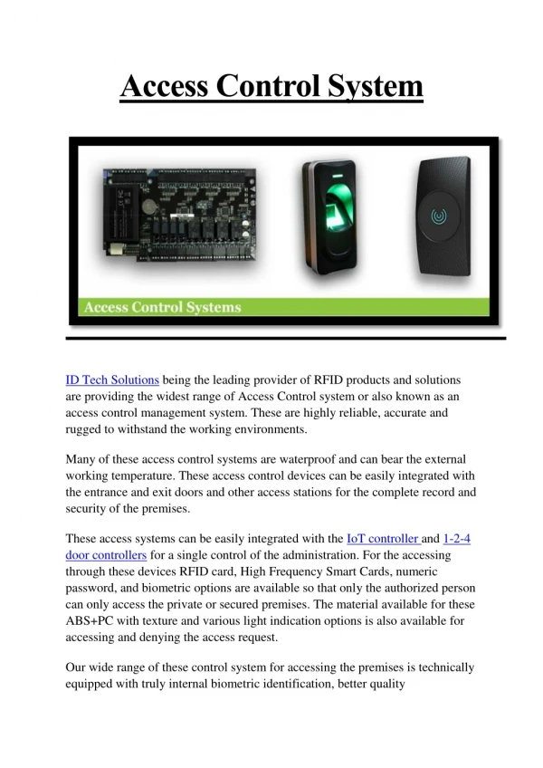
Project overview • The main objective of this project is to provide security in an organization by allowing authorized personnel to enter or to access the door to enter into the organization. • For this purpose the authorized personnel are provided with an RFID card. • This card contains an integrated circuit that is used for storing, processing information, modulating and demodulating the radio frequency signal that is being transmitted. • Thus, once the person shows the RFID card to the RFID card reader it scans the data present on the card and compares it with that of the data present in the system and once it matches it displays the message saying valid and unlocks the door or else states invalid and doesn’t allow the access.
Power supply Step down transformer Bridge rectifier Filter Regulator
Contd.. • The 230V AC supply is first stepped down to 12V AC using a step down transformer. • This is then converted to DC using bridge rectifier. • The AC ripples is filtered out by using a capacitor and given to the input pin of voltage regulator 7805. • At output pin of this regulator we get a constant 5V DC which is used for MC and other ICs in this project.
Microcontroller(PIC16F877A) • High-Performance RISC CPU: • Only 35 single-word instructions. • All single-cycle instructions except for program branches, which are two cycle. • Operating speed: DC – 20 MHz clock input DC – 200 ns instruction cycle • Up to 8K x 14 words of Flash Program Memory, Up to 368 x 8 bytes of Data Memory (RAM), Up to 256 x 8 bytes of EEPROM Data Memory. • Pin out compatible to other 28-pin or 40/44-pin, PIC16CXXX and PIC16FXXX microcontrollers.
Special Microcontroller Features: • 100,000 erase/write cycle Enhanced Flash program memory typical. • 1,000,000 erase/write cycle Data EEPROM memory typical. • Data EEPROM Retention > 40 years. • Self-reprogrammable under software control. • In-Circuit Serial Programming™ (ICSP™) via two pins. • Single-supply 5V In-Circuit Serial Programming. • Watchdog Timer (WDT) with its own on-chip RC oscillator for reliable operation. • Programmable code protection. • Power saving Sleep mode. • Selectable oscillator options. • In-Circuit Debug (ICD) via two pins.
Peripheral Features: • Timer0: 8-bit timer/counter with 8-bit prescaler. • Timer1: 16-bit timer/counter with prescaler, can be incremented during Sleep via external crystal/clock. • Timer2: 8-bit timer/counter with 8-bit period register, prescaler and postscaler. • Two Capture, Compare, PWM modules • - Capture is 16-bit, max. resolution is 12.5 ns • - Compare is 16-bit, max. resolution is 200 ns • - PWM max resolution is 10-bit • Synchronous Serial Port (SSP) with SPI™ (Master mode) and I2C™ (Master/Slave). • Universal Synchronous Asynchronous Receiver Transmitter (USART/SCI) with 9-bit address detection. • Parallel Slave Port (PSP) – 8 bits wide with external RD, WR and CS controls (40/44-pin only). • Brown-out detection circuitry for Brown-out Reset (BOR).
BC547 • The BC547 transistor is an NPN Epitaxial Silicon Transistor. • The BC547 transistor is a general-purpose transistor in small plastic packages. • It is used in general-purpose switching and amplification BC847/BC547 series 45 V, 100 mA NPN general-purpose transistors. • Whenever base is high, then current starts flowing through base and emitter and after that only current will pass from collector to emitter
RFid • Radio-frequency identification (RFID) is an automatic identification method, relying on storing and remotely retrieving data using devices called RFID tags or transponders. • RFID (radio frequency identification) is a technology that incorporates the use of electromagnetic or electrostatic coupling in the radio frequency (RF) portion of the electromagnetic spectrum to uniquely identify an object, animal, or person. • An alternative to bar code. • RFID is also called dedicated short range communication(DSRC)
Contd.. • RFID Benefits Versus Bar Code Labels and Scanning • Eliminates human error • Improves speed and efficiency • Increases information availability and location • Allows enhanced security • Delivers data with or without network connection • RFID Application • Manufacturing • Supply Chain, Logistics & Distribution • Security And Access Control • Parking, Bay And Terminal Management • Tool Collection
relay • A relay is an electrically operated switch. • Current flowing through the coil of the relay creates a magnetic field which attracts a lever and changes the switch contacts. • The coil current can be on or off so relays have two switch positions and have double throw (changeover) switch contacts as shown in the diagram.
Contd.. • Relays allow one circuit to switch a second circuit which can be completely separate from the first. • For example a low voltage battery circuit can use a relay to switch a 230V AC mains circuit. • There is no electrical connection inside the relay between the two circuits, the link is magnetic and mechanical.
Liquid crystal display-lcd • Most common LCDs connected to the microcontrollers are 16x2 and 20x2 displays. • This means 16 characters per line by 2 lines and 20 characters per line by 2 lines, respectively. • The standard is referred to as HD44780U, which refers to the controller chip which receives data from an external source (and communicates directly with the LCD.
Contd.. • If an 8-bit data bus is used the LCD will require 11 data lines(3 control lines plus the 8 lines for the data bus) • The three control lines are referred to as EN, RS, and RW • EN=Enable (used to tell the LCD that you are sending it data) • RS=Register Select. When RS=0; data is treated as a command & When RS=1; data being sent is text data. • R/W=Read/Write . When RW=0; the data written to the LCD & When RW=0; the data reading to the LCD.
Working of project • The project uses a RFID reader that sends a 125 KHz signals while a RFID card is swiped over the same. • The card used gets powered by inductive means with the coil inside the same duely rectified and filtered for a DC voltage to drive the inbuilt chip in the card. • Thus while the card is swiped over sends a valid data to the MC to output a logic high from the MC at pin 16 to switch on transistor which finally actuates the load for example a lamp in this case. • The LCD display indicates all the position occruing in the process.