Assembly Manual
CricketSat Receiver. Assembly Manual. Mike Fortney 04/09/2004. Index. Parts List Parts Layout Completed Board - Top View Circuit Board Assembly Enclosure Modifications Final Assembly Testing Troubleshooting Schematic


Assembly Manual
E N D
Presentation Transcript
CricketSat Receiver Assembly Manual Mike Fortney 04/09/2004
Index • Parts List • Parts Layout • Completed Board - Top View • Circuit Board Assembly • Enclosure Modifications • Final Assembly • Testing • Troubleshooting • Schematic • More sections to be added: Features, Specifications, Circuit Description, Normal Operation, Data Logging with a Computer, Optional Accessories
Parts List (1 of 2) • Verify that you have the following parts in your kit. If not send an email to mfortney@emba.uvm.edu • Use the photo two pages ahead to identify parts • White plastic enclosure with built-in speaker • Antenna • Green printed circuit board • 9-Volt battery • 9-Volt battery snap connector • Power switch • RF receiver module • LM386 IC chip • 8-pin DIP socket • 5-Volt regulator (black 3-pin device) • Red and green LEDs
Parts List (2 of 2) • Two black tubular LED standoffs • Protection diode • Audio jack • External power jack • Blue 220uF coupling capacitor • Five small yellow 0.1uF capacitors • Larger yellow 10uF capacitor • Volume control potentiometer • 10 ohm resistor, brown-black-black-gold • Two 750 ohm resistors, violet-green-brown-gold • 180K ohm resistor, brown-gray-yellow-gold
Parts Layout J3 not installed
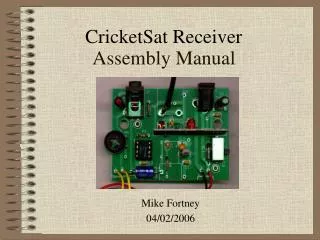
Completed Board - Top View Audio Data Jack Antenna Coax Cable Power Jack Twisted Braid Data LED (Red) Power LED (Green) RF Receiver Module Volume Control Potentiometer Power Switch LM386 Amplifier IC Battery Leads (Red - Right Black - Left) Speaker Leads (Non-Polarized) Coupling Capacitor 5-Volt Regulator (flat side outward)
Circuit Board Assembly (1 of 4) • Refer to layout images on previous pages • Install the parts in the following order: • Resistors • R1 & R2, 750 Ohm, violet-green-brown-gold • R3, 180K Ohm, brown-gray-yellow-gold • R5, 10 Ohm, brown-black-black-gold • 0.1uF capacitors (C1, C3, C4, C5, C7) • D1 diode, banded side is negative (-) • R4, volume control • C2, 10 uF capacitor, banded end is positive (+) , mount close to the board
Circuit Board Assembly (2 of 4) • S1, power switch • IC socket, 8-pin DIP, notch towards R3 • U3, LM386 IC, notch towards R3 • U1, 5-Volt regulator, flat side facing C1, mount as close to the board as possible • C4, 220 uF capacitor, banded end is negative (-), indented end is positive (+)
Circuit Board Assembly (3 of 4) • J1 & J2, power and audio jacks • U2, RF receiver module, mount as close to the board as possible • D2 & D3, red and green LEDs, mount with standoffs, tight to the board • Positive LED lead is the longer of the two leads LEDs with standoffs
Circuit Board Assembly (4 of 4) • 9-Volt battery clip, red (+) and black(-) wires • Antenna coax cable • Cut to 2 inch length • Strip back insulation 1/2” • Separate braid from center conductor, twist into a second wire • Solder into board as shown below and in layout image RF Receiver Module Twisted Braid in big hole DO NOT use this hole Center conductor this hole Top of edge of board
Enclosure Modifications(1 of 2) • Remove the two screws from back of the enclosure and remove the back cover • Drill holes where indicated by the black dots shown below • Center punch the hole first to insure proper alignment • Drill holes using a 1/8 inch drill bit 1/8” holes for the LEDs
Enclosure Modifications(2 of 2) • Cut out the blacken shapes shown below using a nibbling tool, file or a saw • Remove the template stickers once complete and clean rough edges with a file Remove material Remove material
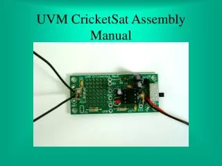
Final Assembly(1 of 2) • Remove two circuit board mounting screws from enclosure • Solder speaker wires to circuit board • Mount antenna into center slot and tighten into place Route battery cables Circuit board mounting screw Guide post and hole Antenna slot Circuit board mounting screw Guide post and hole
Final Assembly(2 of 2) • Fit circuit board into place in following sequence • Use previous diagram to aid in this assembly • Bend RF receiver module slightly towards antenna coax cable • Lower into place, and mate switch lever with plastic thumb slider piece on inside of enclosure • Align and lower circuit board guide holes over enclosure vertical guide posts • Press and wiggle circuit board until LEDs pop through holes of front of enclosure • If problem seating board, check that coax cable is not between RF module and speaker. If so, move cable, and repeat above steps. • Secure circuit board with two screws • Route battery cable, but DO NOT install the battery yet • Attach back of enclosure and secure with screws
Testing • Slide power switch all the way up. It is a three-position switch with only the top position as “ON” • Using a multimeter, perform a short circuit test on the battery clip, reverse the leads and repeat. You should measure no values less than 5K ohms. • Attach the battery and its cover • The unit should be “ON” indicated by the green LED • The red LED may briefly flash as the unit is switched on • Turn the volume control to a mid position and you should hear a hiss from the speaker • Test the unit with a CricketSat. The red LED should mimic the CricketSat LED at distances of 25 to 100 feet
Troubleshooting • No sound or lights, no smoke • Try a new battery • Insure that slide switch is working properly • Check if battery leads correctly attached to board, red +, black - • Check if D1 diode is properly installed, white band - • Check if amplifier IC and RF receiver modules installed properly • No sound, but lights • Turn volume control to a median setting. Should hear hissing sound • Does not receive CricketSat tone or pulses • Receiver module may be faulty or need re-tuning