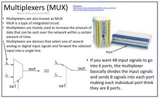
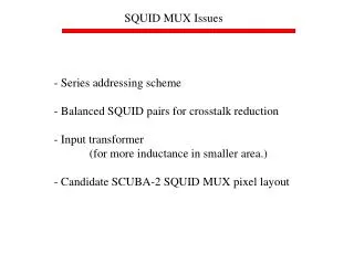
SQUID MUX Issues
SQUID MUX Issues. - Series addressing scheme - Balanced SQUID pairs for crosstalk reduction - Input transformer (for more inductance in smaller area.) - Candidate SCUBA-2 SQUID MUX pixel layout. V SQUID ~ 100 m V I SQUID ~ 100 m A. I OFF < 1/3 I SQUID R || ~ 3 W

SQUID MUX Issues
E N D
Presentation Transcript
SQUID MUX Issues - Series addressing scheme - Balanced SQUID pairs for crosstalk reduction - Input transformer (for more inductance in smaller area.) - Candidate SCUBA-2 SQUID MUX pixel layout
VSQUID ~ 100 mV ISQUID ~ 100 mA IOFF < 1/3 ISQUID R|| ~ 3W RA = 80R|| = 240W for 450 mm l/2D PMUX = 2RA(ISQUID)2x 80 x 4 = 1.5 mW !!! Conventional “Parallel Address” SQUID MUX
NIS address elements to reduce power - High ‘off’ resistance for low crosstalk, leakage - Low ‘on’ resistance for low power
Old NIS Addressed Multiplexer For 450 mm l/2D For Nb NIS junctions D=1.5 mV P=2D ISQUIDx2x80x4 = 192 mW For Al NIS junctions D=0.18 mV P=2D ISQUIDx2x80x4 = 23mW
But... Even with the NIS element, the “parallel” MUX has some issues: - Complicated fabrication: integration of additional NIS steps into our process - A full row of address elements has low resistance (~ 0.1 W). Speed limitation. - High current source required … perhaps tens of milliamps - NIS junctions can’t be tested at 4 K. What we really want is a current-biased, series-address scheme, but putting the elements in series leads to ‘network effects’ that prevent operation.
Series MUX Rs Rs Rs Rs
Series-Address SQUID MUX Instead of adding voltages, add magnetic flux. Then address lines can be series instead of parallel.
Series Address vs. Parallel NIS Address Parallel NIS Series Power few 10’s mW few 10’s mW Fabrication Very hard Somewhat less hard Address lines 10’s of mA < 1 mA Crosstalk Hard voltage bias Hard current bias Address complexity Complex, but doable Simpler Resistance < 0.1 W ~ 20 W (faster) Test temperature 0.1 K 4K
32-Channel Series-Address SQUID MUX Chip In fabrication 32 address pairs 32 input bond-pad pairs
Feedback-Input Coupling Feedback line Comp coil Signal is sent down comp coil to cancel feedback coil – input Coil coupling. Feedback to the pixel which is ‘on’ charges up the input inductors on ‘off’ pixels: a crosstalk mechanism for distant pixels Two solutions: 1) A common ‘Comp coil’ for the column can be adjusted to cancel input-feedback coupling (FIBRE). 2) A balanced SQUID pair with opposite winding will geometrically cancel. Only one SQUID is turned on: the other is just a dummy. TES V
FIBRE Comp Coil 8 channels Nyquist inductor Comp coil
Input Transformer Input More inductance can be put in a smaller area by coupling through a transformer. The input transformer is wound as a gradiometer over a ground plane with a dumbell slit to reduce crosstalk
SCUBA-2 SQUID MUX Pixel Layout Flux output line Feedback line Comp coil? to bump bonds Address Line Input Transformer Balanced SQUID pair; only one is turned on. to bump bonds
SCUBA-2 SQUID MUX Physical Pixel Layout Bump bond? Input Transformer SQUID Input Transformer Output Transformer Dummy SQUID Bump bond?