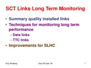
Setting up SCT Links
Setting up SCT Links. Data Links TTC Links Timing in detector Monitoring bit errors. Data Links. Can adjust VCSEL current, Receiver threshold (this is a DC coupled link) Timing wrt receiver electronics (ie phase of local copy of 40 MHz clock).

Setting up SCT Links
E N D
Presentation Transcript
Setting up SCT Links • Data Links • TTC Links • Timing in detector • Monitoring bit errors ATLAS/CMS Opto wg September '08
Data Links • Can adjust • VCSEL current, • Receiver threshold (this is a DC coupled link) • Timing wrt receiver electronics (ie phase of local copy of 40 MHz clock). • In practice set VCSEL current to 10 mA and only change if required (radiation damage). ATLAS/CMS Opto wg September '08
RX threshold/Phase • 2D scan using clock/2 mode of FE module ie i/p 40 MHz clock o/p 20 MHz clock Green 50% “1” good region Clock Delay RX Threshold/10 Set delay to be away from black strip ie edge ATLAS/CMS Opto wg September '08
RX Threshold • Still need separate RX threshold scan using burst data because of non-balanced code Send burst of fixed data pattern ATLAS/CMS Opto wg September '08
RX threshold • Slow-turn on channels Small effect of slow turn-on Very bad channel ATLAS/CMS Opto wg September '08
TX Links • Uses BiPhase Mark (BPM) encoding blanced code. • To set-up links only parameter to adjust is VCSEL current (pin bias set to 6V don’t adjust until needed by radiation damage). • Just set to default 10 mA and leave it until required (radiation damage for p-i-n diodes). • Check that p-i-n current Ipin is reasonable. • Links with balanced codes much easier to set-up and operate! ATLAS/CMS Opto wg September '08
Mark: Space Ratio Adjustment • Non 50:50 MSR jitter in recovered 40 MHz clock Need to adjust MSR. Both edges used to recover 40 MHz clock ATLAS/CMS Opto wg September '08
MSR Optimisation • Use modules in clock/2 mode, look at returned data. • Use chains of inverters to stretch pulse. MSR register settable from s/w. • Set MSR value • Scan receiver phase measure duty cycle of received clock. • Flip phase of BPM signal (send data “1”) and repeat scan. ATLAS/CMS Opto wg September '08
MSR Scans D Duty Cycle Duty Cycle MSR Register MSR Register Use clock delay scan to measure duty cycle before and after flip Plot asymmetry vs MSR ATLAS/CMS Opto wg September '08
MSR Summary • Scans work: • 2 links see same BPM signal agree on optimal MSR register value. • Still need more work to optimise this scan • Finer steps in MSR values • Finer scan of phase using 40 ps steps instead of 1ns steps. • BPM ok for SCT operation (RMS jitter < 1 ns) but difficult to achieve a very low jitter recovered clock eg don’t use 160 MHz BPM signal 3.2 Gbits/s clock. ATLAS/CMS Opto wg September '08
TimingAdjustment • Need to trigger on correct BC! • Need to set clock delay accurately to optimise detector efficiency. • Can adjust • L1 trigger signal in units of 25 ns • BC clock fine delay in units of 0.35 ns • Set-up timing with dead reckoning and verify/scan with beam. ATLAS/CMS Opto wg September '08
Dead Reckoning • Measure propagation delays in cables/chips from trigger o/p to o/p of BPM-12 chip. • Measure propagation times in fibre cables. • Very simple system used: send pulse down one fibre in a ribbon and connect a “reflector ribbon” at the other end to send the light back. Used optical probe/digital scope to measure propagation delay. • Calculate propagation times for short lengths of on-detector fibres. • Correct for time of flight for particles from vertex to detector modules. ATLAS/CMS Opto wg September '08
Trigger Timing with Cosmics Peak at 0 Look at number of coincidences between chip hits from two sides of modules Vary time delay, find maximum coincidences Dead reckoning was correct! SR1 Cosmics ATLAS/CMS Opto wg September '08
22 25 19 16 20 21 BOCdelay M6 timing in for pit cosmics • Scintillator trigger • Threshold: 1.2 fC • Cosmics mode: 3 BC + level hit • Each ROS samples 1/4 barrel • Pause/resume to change BOC delay • Plot # coincidence hits vs event ATLAS/CMS Opto wg September '08
Timing from 1 event: beam splash • Coincident hits from single beam splash event (10/9/08) • Time bits adjust by 2 clock cycles • Coarse timing can (almost) be set with only 1 event! Most hits are 001 Should be mix of 010 and 011 Time bin bits ATLAS/CMS Opto wg September '08
Cosmic Fine Delay Scans • SR1 Cosmic scans • Used trigger scintillator timing • Measure module hit efficiency versus trigger time. • Readout if hit in 3 time bins but record 3 bit time pattern. ATLAS/CMS Opto wg September '08
Fine Delay With Beam • Set fine-delays to calculated values. • Scan fine delay and measure module hit efficiencies. • Make adjustments in groups of 12 modules as we use 12 way ribbons. • Needs 5000 tracks 17000 min bias events ~ 2 hours to perform scan. • Should be very stable? ATLAS/CMS Opto wg September '08
Monitoring Link Errors • Data pattern has some fixed bits (preamble, part of header and trailer). • Send 8 LSBs of L1 and 4 of BC to module, compare with full L1 and BC in ROD. • See few modules with L1 and BC errors but not fixed run to run…under investigation. • Can monitor BER in-situ. ATLAS/CMS Opto wg September '08
Summary • Can set up data and TTC links but DC coupled links much more difficult than • Can optimise MSR for BPM signals to get low enough clock jitter but small jitter will remain. • Timing adjustments ok. • BER can be monitored in-situ. ATLAS/CMS Opto wg September '08