Download
1 / 12
120 likes | 144 Views
Explore different cooling options to maintain chamber temperatures within limits, enhance heat transfer estimates, and optimize cooling capacity. Evaluate manifold design, piping requirements, and potential integration into the RPC structure.

E N D
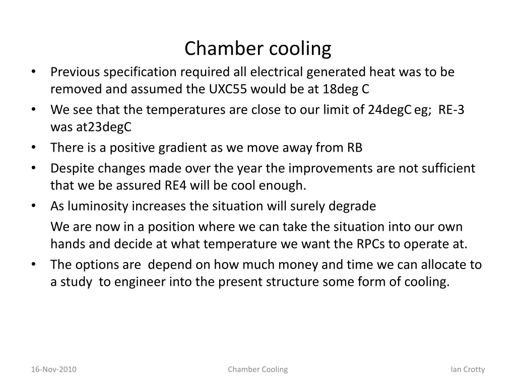
Chamber cooling • Previous specification required all electrical generated heat was to be removed and assumed the UXC55 would be at 18deg C • We see that the temperatures are close to our limit of 24degC eg; RE-3 was at23degC • There is a positive gradient as we move away from RB • Despite changes made over the year the improvements are not sufficient that we be assured RE4 will be cool enough. • As luminosity increases the situation will surely degrade We are now in a position where we can take the situation into our own hands and decide at what temperature we want the RPCs to operate at. • The options are depend on how much money and time we can allocate to a study to engineer into the present structure some form of cooling. Chamber Cooling
Endcap temperatures during 2010 Approx 0.5 deg C gain Chamber Cooling
First approach • Luc and Walter proposal for increasing the present FEB cooling to cool the chamber volume. Chamber Cooling
Integrated cooling • Can we cool the structure of the chamber ? • Do we need to cool both faces ? • We need thermally conductive materials Chamber Cooling
Heat Transfer estimates . What is the size of the problem ? Q = h.A (TRPC – Tamb) h= 5-15[W/m2C] RPC @ 18°C Ambient temp. 2 cases; 23°C & 28°C CSC @ 23°C Internal Heat generation < 1W/RPC @ 1034 Radiaitive heat transfer = few watts Convective heat transfer = ~300W/10degRPC @ 23°C amb. = ~600W/10deg/RPC @ 28°C amb. Chamber Cooling
Cooling capacity per Circuit • Using present flow restrictors (0.5 US gap/min) = 1.9l/min • Assume ∆T of 2°C. This is of course too high as we specify a ∆T of 2 deg throughout the chamber, but it gives an upper bound, allowing us to continue the estimates. • Q = m. Cp. ∆T This gives a max thermal power dissipation of 265W. Almost sufficient for 1 10° sector of RPC for ambient = 23°C • Removing 300W/RPC sector gives 300. 36 = 10.8kW almost an order of magnitude above the design value. • The manifold has a design capacity of > 15kW @ ∆T 1.4°C. This doesn’t look so good. Chamber Cooling
Manifold Design by CSC Team Flow values are approx 85% of design Chamber Cooling
How much piping do we need on the face of the RPC • Or how far apart do the pipes have to be ? • Assuming a simple “fin calculation” with insulated end • Q = N(K.A.n ∆T). Tanh (nh) for just one side of the fin. • Q = 7.5W/m each side of the pipe. • With 10m (RE*/3) + 5m(RE*2) = 15m on each face per sector gives 225W. • Still in the ball park of 300W/sector. Pipe spacing ~ 200mm ? Copper (?) cooling pipe 1mm thick Alu fin “L” Chamber Cooling
Pipe spacing virsus ∆T performed by Alvaro.Villa.Recio@cern.ch Chamber Cooling
Concluding so far • We can remove some hundreds of watts of each 10deg RPC sector. • Rolling of Cu pipe to reduce height increases contact patch using tool in 904. • We can maintain a ∆T < 2°C between piping with a spacing of almost 300mm. • All the above assumes that thermal resistances between cooling circuits and the RPC structure can be kept low. • Can the above be incorporated into the RPC honeycomb (HC) structure ? • We must build a real model. Chamber Cooling
Cooling connection between chambers in a 10deg sector Top View RE*2 Union linking HCs RE*3 Zoom X-Section HC Gaps Cooling Pipes HC Chamber Cooling
Steps to validate the principle • Measure the ∆P for a pipe fitting inside the present HC = 5mm inside. • Calculate for 10m dia 6mm = 1.8bar (new) 4 bar (old), already high. • Calculate for 10m dia8mm = 0.2 – 0.5bar • The pipe must be rolled to reduce the height to 5mm. Tests to check the spread in ∆P due to error in rolling of the pipe. • Check for availability/cost of rectangular copper pipe ! • Fabricate HC panel 1m wide to verify the ∆T in a real construction using IR camera or other instrumentation. Skin thickness increased on one side from today’s 0.5mm to 1mm. • The HC panels can be vac. bagged on the marble in the ISR as done for TT to PK Full scale prototype HC panel with cutouts etc for production feasibility, thermal and integration studies. The 5mm HC was ordered 25 Jan 2011. The rolling of the Cu pipe can be done in 904.skins will come from CERN stores. Chamber Cooling