Download
1 / 1
10 likes | 105 Views
Design and feasibility phases of a miniature CCD camera system for intrinsic optical imaging of the cortex, aiming to reduce limitations in experimental paradigms. The system allows for awake imaging and minimal physical restraints on subjects.

E N D
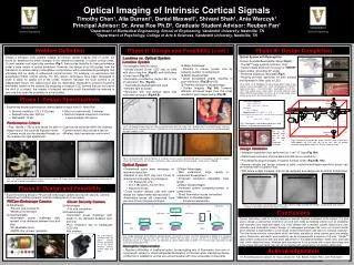
Optical Imaging of Intrinsic Cortical Signals Timothy Chen1, Alia Durrani1, Daniel Maxwell1, Shivani Shah1, Ania Warczyk1 Principal Advisor: Dr. Anna Roe Ph.D2, Graduate Student Advisor: Reuben Fan1 1Department of Biomedical Engineering, School of Engineering, Vanderbilt University, Nashville, TN 2Department of Psychology, College of Arts & Sciences, Vanderbilt University, Nashville, TN Light Source Light source A B C CCD Lens 2.5 cm Light source Lens Light source CCD CCD S1_2 = 4.00 cm 8.50 cm Membrane Membrane Membrane VideoUSB Converter S1 = 3.40 cm Brain Brain Brain A B C 10 cm S1_1 = 7.00 cm 6 cm Reflected Light 15.75 cm C A D E B A B C • Established desired performance criteria based on input from Dr. Anna Roe • Desired resolution: 512 x 512 pixels • Desired frame rate: 300 fps • Well depth: 12 bits • Must run continuously: 5 minutes • Must not impede movement of animal: • approximately 300 grams A B A B C A B C 1 cm 1 cm PillCam Endoscope Camera: Clover Security Camera • Advantages: • Fits into size constraints • Wireless transmission • Disadvantages: • Illumination posed challenge; light needed to be delivered between lens and chip • No adjustable focus • CMOS chip lower resolution • Advantages: • Fits size constraints • Disadvantages: • Illumination poses challenge: light needs to be delivered between lens and chip • Poor resolution due to inadequate CCD chip • Not wireless Problem Definition Phase II: Design and Feasibility (cont.) Phase II: Design and Feasibility (cont.) Phase III: Design Completion • Optical System with Beamsplitter • Custom Scalable Beamsplitter Setup (Fig 8): • ThorlabTM cage systems hold lens, chip. • Custom-made aluminum housing for 75R/25T beam-splitter (providing 45o angle) • Preferred distances calculated (Fig 7) • Housing provides apertures for both subject and illumination (fiber optic or LED) Design a miniature CCD camera suitable for intrinsic optical imaging (IOI) of cortex. IOI works by detecting the small changes in the reflective properties of active cortical areas. Current systems use large bulky cameras (Fig 1) that provide flexibility for high performance under a wide variety of optical conditions. However, the design of an IOI system from the standpoint of camera design necessitates compromises within experimental paradigms that ultimately limit our ability to understand cortical function. For example, it is well known that anesthesia inhibits cortical activity. For this reason, techniques have been developed in order to allow for awake IOI of the cortex. However, because the CCD camera is an independent fixture, the subject must also be reasonably restrained to prevent excessive movement relative to the camera. By designing a miniature CCD camera that can be fixed to the skull of a subject, the number of physical restraints could theoretically be reduced to zero and thus open the possibility to novel studies. Lensless vs. Optical System Lensless System • Major Advantage: • Potential to reduce system size by reducing number of components • Major Disadvantage: • Large acceptance angles resulting in poor resolution. (Fig 3B and C) • Potential Solution to disadvantage: • Contact imaging (Fig 3A); however,attempts at tissues larger than thin slices resulted in poor image quality (Fig 3B) • Investigated need for optics • Directly placed Clover CCD chip on slide with slice of pig liver (Fig 4C) and solid piece of liver tissue (Fig 3C). • Illumination provided by single LED or ring of red/green LEDs (Fig 4C). • Transmitted/reflected light both used. • Ambient light excluded • Resolution with and without optics was estimated using grid (Fig 4A,B). Fig 6 (right). (A, B) SolidWorks design of beamsplitter holder. Arrow indicates where beamsplitter lies. (C,D) Configuration of ThorlabTM cage system parts – from left to right – beamsplitter, 2.6 cm lens, CCD Chip; yellow arrow is light signal, red arrow reflected signal hitting 75R/25T beamsplitter (E) Close up of custom-made mount (yellow arrow shows where beamsplitter lies). Phase I: Design Specifications A B • Thin Lens Equation: • 1/S1 + 1/S2 = 1/f • 1/S1 + 1/11 cm = 1/2.6 cm • Solution: • S1 = 3.40 cm • Magnification: M = -S2/S1 = -3.22 • To map well size onto CCD, set minimum chip width: • w = 2*r • w/2r = M = -S2/S1 • Fig 7.Calculations used to obtain object-lens-chip • distances, and projected magnification. Performance Criteria • Size: Ideally < 300 g and would be able to image most of the currently exposed cortex. • Camera would use the standard threads on • the chamber for rigid attachment. • Light source would be within the chamber. • Camera would only protrude a few cm • Wireless data transmission and control Fig 3:(A) Contact Image of pig liver slide; transmitted white light with single LED. (B) White light transmitted through solid liver piece liver to CCD in contact with tissue. (C)Solid liver tissue imaged through cover slip with lensless setup. Illumination provided by ring of red/green LEDs. Fig 9. (A) ThorlabTM cage with 2.6 cm lens (B) cage with 1/3” Panasonic CCD chip C A B C Fig 8. Schematic of final design setup. ThorlabTM cage system parts hold together (A) CCD chip, (B) 2.6 cm lens, and (C) custom aluminum beamsplitter holder (VU Physics machine shop). A B Design Validation • Validation experiment first performed on 1 cm2 “V” logo (Fig 10A) • Determined resolution of 6 line pairs/mm (83 micron resolution) • Proceeded to acquire images of squirrel monkey cortex (Fig 10B, 10C). • Results indicate that design scheme is valid; resolution/well-depth/sensitivity issues can be resolved with a superior chip. • With future budget increase, chip can be replaced, and design can be further miniaturized. Fig 4:(A) Reflected light from test pattern (1 mm grid), lensless system. (B) Reflected light from test pattern, single lens system (Clover Security Camera, 3.6 mm lens). (C) Pig liver slide used with direct-contact imaging – image shown in Fig 3A Optical System • Major Advantages: • Well understood, large variety in component development • Increased resolution; adjustable focal length • Major Disadvantages: • Increased system complexity/number of components • Direct illumination issues unresolved • Solution to Disadvantages: • Introduce beamsplitter • Determined optics were necessary for maximum resolution • Decided to use CCD chip from Clover to determine functionality of prototype(s) • 1/3” Panasonic Chip • 512 x 492 pixels, 3.6 mm lens • maximum 30 fps • Could feasibly replace chip with same design (for higher frame rate/resolution) • Illumination issues still unresolved (from previous Clover Camera prototype) Fig. 1: (A) Current method to capture images of cortical signals. (B) Images obtained; post green light to map vasculature and (C) post red light to project hemodynamic activity. Phase II: Design and Feasibility • Explored existing designs: PillCam SB endoscope camera and Clover security camera. • Determine if existing systems could be redesigned to fit out needs. Fig 10:(A) Test image using design with ambient light. (B) Test image acquired with red light. (C) Resolution grid showing maximum of 6 line pairs per mm (83 micron resolution) Conclusions • Current technology used for cortical imaging in animals impedes movement of the subject. Our goal was to design a camera that minimizes size and cost, while considering criteria such as scalability, high resolution and large well depth. Our initial attempt with a lensless system failed due to poor resolution and illumination issues. Design of subsequent prototypes led us to our current model, which employs a beamsplitter to solve issues of direct illumination, and optics to increase resolution. The final model contains components which are easily scalable by using custom parts and smaller optics. Resolution, well depth, and sensitivity can be increased with a superior CCD chip. ThorlabTM cage system components with rails allow adjustment of the distance between object, lens, and CCD chip, which determine focus. Wireless data transmission is not possible with current technology due to the image size and frame rate, but will be feasible with advancement of wireless technology. Fig. 2 (A): Diagram of PillCam SB; (B) Clover security camera positioned on rat; (C) Clover miniature security camera, black and white. A B C Fig.5: Simple Schematics of the different possible designs. (A) Lensless system. The CCD chip would sit directly on a transparent membrane. Transmitted light must be used – but only effective with thin slices of tissue. (B) This is essentially a simplified and miniaturized version of a modern system. (C) Utilization of a beam splitter allows for better use of the 3D space and allows for light source to be directly above ROI. Beamsplitter Implementation Acknowledgements • Resolves difficulties of traditional optics: by decoupling axis of illumination from axis of focal length, allows for direct/unimpeded illumination of the brain while maintaining device profile that is suitable for animal use and achievable with more accessible components. Dr. Anita Mahadevan-Jansen,Dr. Duco Jansen, Dr. A.B. Bonds, Chaten Patil, John Fellenstein