Download
1 / 41
420 likes | 566 Views
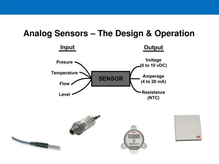
Analog Sensors – The Design & Operation. HVAC Sensors. Sensors measure the controlled medium and provide a controller with information concerning changing conditions in an accurate and repeatable manner. The common HVAC variables are temperature, pressure, flow rate and relative humidity.

E N D
HVAC Sensors Sensors measure the controlled medium and provide a controller with information concerning changing conditions in an accurate and repeatable manner. The common HVAC variables are temperature, pressure, flow rate and relative humidity.
HVAC Sensors • The placement of a sensor is critical to achieve good control. In sensing space conditions, the sensing device must not be in the path of direct solar radiation or be located on a surface which would give a false reading such as a poorly insulated external wall. • In pipework or ductwork, sensors must be arranged so that the active part of the device is immersed fully in the fluid and that the position senses the average condition.
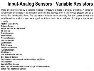
Types of Inputs Digital Input Two position, a simple contact closure from a mechanical switch or similar device Analog Input Modulating, the signal is proportional and varies with the control variable Pressure • Temperature Event • Level • Flow
Types of Analog Inputs • Typical sensors used in electronic control systems are: • Resistance sensors are ‘Resistance Temperature Devices (RTD’s) • Voltage sensors could be used for temperature, humidity and pressure. Typical voltage input ranges are 0 to 5 Vdc (Volts direct current), 1 to 11 Vdc, and 0 to 10 Vdc, 2 to 10 Vdc. • Current sensors could be used for temperature, humidity, and pressure. The typical current range is 4 to 20 mA (milliamps) or 0 to 20 mA
Types of Analog Inputs Active Require an external source (voltage or current) of excitation Passive Are two-port devices that directly transform physical energy to electrical energy, generating output signals without the need for an excitation source. Thermistors Strain Gage Thermocouple Photodiode RTD
Thermocouples (Passive) • Thermocouples have two dissimilar metal wires joined at one end. • Temperature differences at the junctions’ causes a voltage, in the mill volts (Seebeck Effect) • The output is a voltage proportional to the temperature difference between the junction and the free ends
Thermocouples • By holding one junction at a known temperature (reference junction) and measuring the voltage, the temperature at the sensing junction can be deduced. • The voltage generated is directly proportional to the temperature difference.
Thermocouples • Advantages: Widest operating range, simple, low cost and no external power supply required • Disadvantages: Non-linear, low stability relative to other types, reference junction temperature compensation required
Thermocouples – Various Types (Active) Type K = 41µV/˚C Seebeck Coefficient is Nonlinear
Thermistors • Thermistors are temperature sensitive semiconductors that exhibit a large change in resistance over a relatively small range of temperature. • There are two main types of thermistors, positive temperature coefficient (PTC) and negative temperature coefficient (NTC). • NTC thermistors exhibit the characteristic of falling resistance falling with increasing temperature.
Thermistors • They are non-linear, and cannot be characterized by a single coefficient. Manufacturers commonly provide resistance-temperature data in curves, tables or polynomial expressions • Linearizing the resistance-temperature correlation may be accomplished with analog circuitry, or by the application of mathematics using digital computation
Thermistors • Advantages: Large resistance change with temperature, rapid response time, good stability, High resistance eliminates difficulties caused by lead resistance, Low cost and interchangeable • Disadvantages: Non-linear, limited operating temperature range, may be subjected to inaccuracy due to overheating, current source required
RTD (Resistive Temperature Device) • RTD (Resistance Temperature Detector) is a temperature sensitive resistor • It is a positive temperature coefficient device • Common materials used are BALCO wireand Platinum • Advantages • Very predictable • Stable output over a long period of time • Easy to recalibrate • Accurate reading over relatively narrow temperature range
Balco • A sensor constructed using a BALCO wire is an annealed resistance alloy with a nominal composition of 70 percent nickel and 30 percent iron. • A BALCO 500-ohm resistance element provides a relatively linear resistance variation from –40 to 250°F. • The sensor is a low mass device and responds quickly to changes in temperature. • When 1000 ohms is measured across the BALCO element, the temperature is approximately 70°F. • As the temperature increases, the resistance changes 2.2 ohms per 1°F.
Platinum • RTD sensors using platinum material exhibit linear response and stable over time. • In some applications a short length of wire is used to provide a nominal resistance of 100 ohms. • However, with a low resistance value, element self-heating and sensor lead wire resistance can effect the temperature indication. With a small amount of resistance change of the element, additional amplification must be used to increase the signal level.
Humidity Sensor - Resistive • Relative humidity based on a layer of hygroscopic salt, such as lithium chloride or carbon powder deposited between two electrodes • Both materials absorb and release moisture as a function of the relative humidity, causing a change in resistance of the sensor • An electronic controller connected to this sensor detects the changes in resistance which it can use to provide control of relative humidity
Humidity Sensor - Capacitive Humidity Sensor - Capacitive • Changes in capacitance can be used to determine relative humidity • This sensor measures the capacitance between two conductive plates separated by a moisture sensitive material such as polymer plastic • As the material absorbs water, the capacitance between the plates decreases and the change can be detected by an electronic circuit
Pressure Sensors • Diverse electrical principles are applied to pressure measurement. • Those commonly used include capacitance and variable resistance (piezoelectric and strain gage)
Pressure Sensors - Resistive • A method that measures pressure by detecting changes in resistance using a small flexible diaphragm and a strain gage assembly • The strain gage assembly includes very fine (serpentine) wire or a thin metallic film deposited on a nonconductive base • The strain gage assembly is stretched or compressed as the diaphragm flexes with pressure variations. • The stretching or compressing of the strain gage changes the length of its fine wire/thin film metal, which changes the total resistance. • The resistance can then be detected and amplified.
Pressure Sensor - Capacitive • A fixed plate forms one part of the capacitor assembly and a flexible plate is the other part of the capacitor assembly • As the diaphragm flexes with pressure variations, the flexible plate of the capacitor assembly moves closer to the fixed plate and changes the capacitance.
Testing an Analog Input – Thermistor • Use an ice bath to test thermistors • Solutions allows a known temperature for the test • Crushed ice works best • Fill container with as much ice as possible • Then fill with water (distilled water if possible) • Let solution stabilize for several minutes to allow ice an water to stabilize at 32˚F
Testing an Analog Input – Thermocouple • There are two steps to checking thermocouples. • The first is to check for a short on its terminals • And the second, to make sure that voltage tracks with the temperature.
Testing an Analog Input – Thermocouple Put the meter in ohms or continuity mode; on a good thermocouple, you should see a low resistance reading. If you see more than a few ohms, you probably have a faulty thermocouple
Testing an Analog Input – Thermocouple The second test requires a meter that can measure down to tenths of millivolts (0.0001 V). A meter that can measure hundredths of millivolts (0.00001 V) makes it even easier to do this check, because the added resolution shows very small temperature changes. Connect the meter to the terminals of the thermocouple. Grabbing the end of the thermocouple should cause the voltage to increase slightly, since you're warming it up. As you release the junction, the temperature (and voltage) should drop
Testing an Analog Input - 4 to 20 mA / 0 to 10 vDC Manometer
Testing an Analog Input - 4 to 20 mA / 0 to 10 vDC Check its Wiring Per the Manufacturers Wiring Diagram
Check Setting of Sensor, if applicable Sensor should be set for 0 to 1“ operation Follow Manufactures Guidelines • Set PJ3 at L position and PJ5 at N position • Zero out the sensor by removing any hoses from the two barbs and holding in the zero button for 4-5 seconds
Testing an Analog Input - 4 to 20 mA Manometer
Example Manometer 0.5 in. w.c. Sensor Range = 0 to 1 in. w.c.
Example Manometer 0.5 in. w.c.
Example Sensor Range 0 to 100 psig
Example Sensor Range 0 to 100 psig
Selecting Replacement Sensors • Normally best to use an OEM replacement • If resistive based, determine type and characteristics • If current or voltage, determine the required range and required output signal
Getting Help Read the controller’s manual Call the manufacture