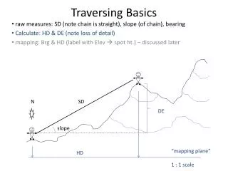
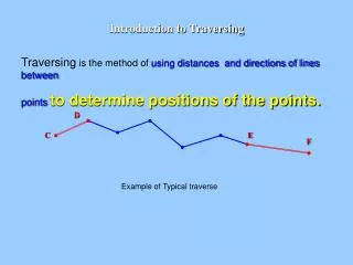
Introduction to Traversing
D. C. E. F. Introduction to Traversing. Traversing is the method of using distances and directions of lines between points to determine positions of the points. Example of Typical traverse. Types of Traverses. I. Loop Traverse. Distance and angles measured. II. Link Traverse. D. C.

Introduction to Traversing
E N D
Presentation Transcript
D C E F Introduction to Traversing Traversing is the method of using distances and directions of lines between pointsto determine positions of the points. Example of Typical traverse
Types of Traverses I. Loop Traverse Distance and angles measured II. Link Traverse
D C E F Types of Link Traverses B A G H Special case of the traverse
Typical sequence of computing Procedures • Adjustment of Angles • Compute Azimuths • Adjustment of distances (Latitudes and Departures) • Compute Coordinates
A 1 orientation point Left angle 1 1 Left angle B Orientation Point with known X,Y Traverse leg d1-2 1 dB-1 d1-2 B 2 orientation point 2 Traverse Station with unknown X,Y Compute direction
Adjustment of Angles in a Loop Traverse • Adjustment of Angles Check Interior Angle Closure ObservedAdjusted A =1010 24’ 00” 1010 24’ 12” B = 1490 13’ 00” 1490 13’ 12” C = 800 58’ 30” 800 58’ 42” D = 1160 19’ 00” 1160 19’ 12” E = 920 04’ 30” 920 04’ 42” Total = 5390 59’ 00” = 5400 00’ 00” Should = 5400 00’ 00” = (n-2)*180 Misclosure = 01’ 00” = 60” Adjustment = 60/5 = +12” per angle B 382.20 C N510 22’00”E 1490 13’00” 401.58 800 58’30” A 368.28 1010 24’00” 1160 19’00” 920 04’30” 350.10 D 579.03 E
Compute Azimuths Ap A An 1 B Ap 180 An= Ap + – 180 An = Ap– + 180 Compute next azimuthsAn
Compute Azimuths Compute Azimuths in Loop traverse aAB = 510 22’ 00” (given) aBA = 2310 22’ 00” B = 1490 13’ 12” aBC = 820 08’ 48” aCB = 2620 08’ 48” C = 800 58’ 42” aCD = 1810 10’ 06” aDC = 10 10’ 06” D = 1160 19’ 12” aDE = 2440 50’ 54” aED = 640 50’ 54” E = 920 04’ 42” aEA = 3320 46’ 12” aAE = 1520 46’ 12” A = 1010 24’ 12” aAB = 510 22’ 00” Check B 82° 08’ 48” C 510 22’00” 1490 13’12” 800 58’42” A 181° 10’ 06” 1010 24’12” 1160 19’12” 920 04’42” D 332° 46’ 12” 244° 50’ 54” E
AB-1 = AAB+B –180 A1-2 = AB-1+1 –180 A2-3 = A1-2+2 –180 A3-C = A2-3+3 –180 ACD = A3-C+C –180 ACD = AAB+[left]–n180 ACD = AAB- [right]+n180 • Adjustment of Angles Should = AK – AP + n180 or (AP – AK + n180 )Misclosure = [ left ] – (AK – AP + n180 ) or [ right ] - (AP – AK + n180 ) II. Link Traverse [left] = AK – AP + n180 [right] = AP – AK + n180 B 2 C A B 2 3 1 C d2-3 dB-1 d3-C d1-2 3 1 D Diredctin of the calculations Bilateral traverse typical Adjustment of Angles in a Link Traverse
D C E F • Adjustment of Angles Adjustment of Angles in a Link Traverse Sum angles Should be = AK – AP + n180 or AP – AK + n180 Misclosure = [ angles left ] – (AK – AP + n180 ) or [angles right ] - (AP – AK + n180 ) Correction to angles = - Misclosure /number of angles
Link (open) Traverse • Compute Azimuths 170-26-15 170-26-20 O2 O1 Traverse Station with unknown X,Y Traverse Terminal with known X,Y Orientation Point with known X,Y 355-40-45 T1 T3 B 355-40-40 80-22-26 110-36-42 75-20-30 T2 111-25-29 82-25-20 260-22-30 290-36-40 255-20-36 262-25-26 291-25-24 A 600.556 500.364 625.484 480.253 674.374 T4 170-26-10 170-26-15 O2
Latitudes (DY) and Departures (DX) Latitude = L Cos a = DY Departure = L Sin a = DX DX T2 DY L a T1 Latitudes and Departures computed for each leg of a traverse
Adjustment of distances (Lats and Deps) Compute Lats (D Cos a) and Deps (D Sin a) Leg Azimuth Distance Lat Dep AB 510 22’ 00” 401.58 250.720 313.697 BC 820 08’ 48” 382.20 52.222 378.615 CD 1810 10’ 06” 368.28 -368.203 -7.509 DE 2440 50’ 54” 579.03 -246.097 -524.130 EA 3320 46’ 12” 350.10 311.301 -160.193 Total -0.057 0.480 Total Traverse Distance = 2081.19 Linear Misclosure = (0.057)2 + (0.480)2 = 0.483 Precision = 0.483/2081.19 = 1/4305 …… 1/4300
Adjustment of distances (Lats and Deps) Correction to Lats = - Traverse leg distance * Lat Misclosure Total traverse distance Correction to Deps = - Traverse leg distance * Dep Misclosure Total traverse distance Leg Lats Deps Corrn Lat Corrn Dep Adj Lats Adj Deps AB 250.720 313.697 0.011 -0.093 250.731 313.604 BC 52.222 378.615 0.010 -0.088 52.232 378.527 CD -368.203 -7.509 0.010 -0.085 -368.193 -7.594 DE -246.097 -524.130 0.016 -0.134 -246.081 -524.264 EA 311.301 -160.193 0.010 -0.081 311.311 -160.274 Total 0.057 -0.481 0.000 0.001