Download
1 / 16
210 likes | 469 Views
The use of Simulink and SimMechanics in the development of vehicle test systems. Andrew Plummer Instron Ltd, UK andrew_plummer@instron.com. Materials & component testing machines. Hydraulic catapult for vehicle crash testing Control using an inverse dynamic model

E N D
The use of Simulink and SimMechanics in the development of vehicle test systems Andrew Plummer Instron Ltd, UK andrew_plummer@instron.com
Materials & component testing machines
Hydraulic catapult for vehicle crash testing Control using an inverse dynamic model Full vehicle test rigs for road/track simulation Modelling for performance verification Real-time models for control Overview
3-Stage Servovalve 4th Valve Stage Sledge Accumulator Rail Longitudinal Accelerometer Actuator Hydraulic Oil Hydrostatic Bearing Crash testing catapult
Valve command signal Longitudinal car acceleration Simulink Model Modelling system dynamicsForward model
Target acceleration Valve command signal Inverse Dynamic Model Calculating command signal
Calculating command signal Target acceleration Valve command signal Inverse Dynamic Model
F1 track simulationTo minimise lap time by assessing alternative designs and set-ups.
Test rig control concept Car and rig Up to 28 hydraulic actuators Control System Valve drives Standard digital controller (8800) • Specialised control functions • via Simulink Real-Time Code Sensors Virtual systems, e.g. aero model
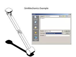
Performance simulation - Simulink and SimMechanics Car and rig Control System Hydraulic system SIMULINK MODEL Valve drives Standard digital controller SIMULINK MODEL Rig mechanics SimMECHANICS MODEL • Specialised control functions • SIMULINK MODEL Sensors Car mechanics SimMECHANICS MODEL Virtual systems, e.g. aero model
Control performance Results Kinematics - e.g. joint angles Forces (joints, actuators etc.)
Obtaining mechanical design information loads, displacements (clashes) System performance prediction comparison with specification perform virtual acceptance tests assess and refine controller, hydraulic and mechanical design Avoid expensive re-work !! Benefits of simulation
Control system and mechanical multi-body simulation in a unified environment Increased simulation speed Some parts of control system already designed using Simulink ready for code-generation Advantages of Simulink for rig simulation