Download
1 / 18
180 likes | 193 Views
This presentation outlines the scope and layout of the vacuum system for the main linac and transfer lines. It discusses the vacuum requirements, sectorisation, and specific issues such as the vacuum chamber of the main quadrupoles and waveguide flanges. Three vacuum technologies under study for the CLIC complex are also mentioned.

E N D
Vacuum requirements and preliminary design of vacuum system for module and transfer lines C. Garion CERN/AT/VAC
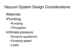
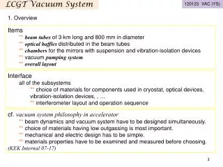
Outline • Scope of the presentation • Main linac vacuum system • Layout and vacuum requirements • Sectorisation • Vacuum system • Dynamic vacuum in accelerating structures • Specific issues: vacuum chamber of the main quadrupoles, waveguide flanges • Long transfer lines • Vacuum requirements • Sectorisation • 3 vacuum technologies under study
CLIC complex 2 main linac 2 long transfer lines ~ 200 km of UHV lines!
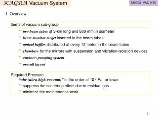
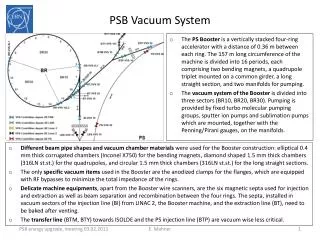
Main linac layout & vacuum requirements 1 main linac is composed of 10462 two beam modules, mainly of 4 types. Accelerating structures Quadrupole Main beam Main quadrupole Drive beam Power extraction system Type 1 module • Beam dynamics requirements: • pressure : ~10-8 mbar • inner diameter of vacuum chamber (main quadrupole) ≥ 3mm • copper beam line (or copper coated)
Main linac Vacuum system sectorisation • Why a sectorisation? • Piece wise installation/commisionning • Ease local intervention for machine maintenance • Ease localisation of leak • Containment of accidental vacuum degradation A manageable sector of 200m is proposed for the main linac.
Main linac Several versions being studied: Disk/quadrant accelerating structures Sealed/tank
Main linac Vacuum equipment (version sealed disk): manifolds around the accelerating structures linked to a common tube pumping system: mobile turbomolecular station + holding ion pumps Manifold Ion pump Ion pump Large manifold
Pumping system (quadrant accelerating structures with tank): static vacuum: mobile turbomolecular station + holding ion pump (+ sublimation?) dynamic vacuum (breakdown of the cavities): tank around the accelerating structures Main linac Pump(s) Tank Pumps
Main linac Assumption: 1012 H2 molecules released during a breakdown Gas load depends on the surface pretreatment and has to be confirmed (measured) Monte Carlo simulation implemented in a FE code (Castem) Dynamic vacuum in the accelerating structures
Main Linac Vacuum chamber of the main quadrupoles • Constraints • Very tight space available low conductance • Unbaked system vacuum is driven by water pumping Proposal: • Stainless steel vacuum chamber, squeezed in the magnet • NEG strips sited in 2 antechambers Aperture radius: 4mm Stainless steel, 0.3 mm thick Spacer NEG strip Ceramic support 8 mm 50 mm
Main LinacVacuum chamber of the main quadrupoles Design Pressure in the central part is determined by the gap reduce the sheet thickness Experiment in progress on a 1.5m prototype Stability study
Flange Gasket Δ Symmetry w New CLIC design concept Main Linac Waveguide flanges • A new design has been proposed to reduce the RF attenuation (smooth transition) and the cost • Gasket deformation • Plastic strain field • Contact pressure • FE model 0.031 mm Flange Flange • Tests and optimization are in progress Gasket Gasket -0.022 mm Initial position -0.05 mm Flange Flange
Long transfer lines Layout: Mainly FODO cells with quadrupoles and drift tubes (Lcell_main=438m, Lcell_drive=109.6m) sectors of ~400m ( 438m) Beam dynamics requirements: Pressure: 10-10 mbar copper beam line (low resistive wall) Inner diameters: 6 cm for the main beam and 10 cm for the drive beam ~80 km cost optimized solution is required 3 possibilities have been considered: ion pumps, NEG coated vacuum chamber + ion pump NEG strips + ion pump
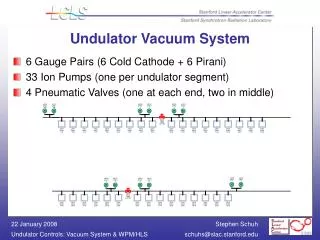
Long transfer lines Holding ion pumps: 1 ion pump (60l/s/10m) Advantages: • Simple tubes no influence on the beam • No bake out needed • Easy for the operation/maintenance • Good control of the pressure along the line Drawbacks: • Discrete pumping • Price QUAD Beam tube QUAD
Long transfer lines Coated vacuum chamber + ion pump (60l/s/10m) QUAD NEG coated beam tube QUAD Advantages: • Distributed pumping Drawbacks: • Time/cost for the conditioning. • Thermal strain during bake-out and activation (additional bellows required) • Influence on the beam under study
Long transfer lines Advantages: Distributed pumping Reduced time/cost for the conditioning. Low influence on the beam Drawbacks: Thermal strain during bake-out and activation (additional bellows required) Reduced pumping capacity NEG strip Insulator (glass fiber braid) NEG strip: NEG strip is used as a pump but also as an heater QUAD Beam tube with NEG strips QUAD
Long transfer lines Preliminary results: Over cost of one solution with respect to the others (does not include supports, tubes, flanges, valves, bellows…) Integration: space has to be reserved for the vacuum equipment (pumps, sector valves)
Conclusions & perspectives A first layout of part of the vacuum system has been proposed for the main linac. Dynamic vacuum due to a breakdown in the cavity is being analyzed for different accelerating structure configurations. Study of the composition and the amount of gaz has to be done as well as the comparison of the time constant in the actual CLEX test stand. Study and tests are on going for the main quadrupole vacuum chamber and the waveguide flanges. Sectorisation of the transfer line has been defined. The technological solution for the pumping system remains to be defined. (If the NEG strip version is promising, make a mock up)