Download
1 / 19
190 likes | 378 Views
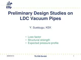
Preliminary Design Studies on LDC Vacuum Pipes. Y. Suetsugu, KEK. Loss factor Structural strength Expected pressure profile. Loss factor. Base Model. LDC_1. Sharp edge. Loss factor. Model for calculation. Total length = 3.8 m D z = 0.1 mm D x = D y = 0.5 mm Axisymmetrical (2D).

E N D
Preliminary Design Studies on LDC Vacuum Pipes Y. Suetsugu, KEK • Loss factor • Structural strength • Expected pressure profile TILC08-Sendai
Loss factor • Base Model LDC_1 Sharp edge TILC08-Sendai
Loss factor • Model for calculation Total length = 3.8 m Dz = 0.1 mm Dx = Dy = 0.5 mm Axisymmetrical (2D) Beam Out In IP f70 pipe Calculate for sz = 2 - 9 mm Extrapolate to sz = 0.3 mm (Due to limited memory and time) TILC08-Sendai
Loss factor • Results ktotal (two beams) ~7x10¹³ V/C @ sz = 0.3 mm If q = 3.2 nC, Nb = 5400 bunch, and fr = 5Hz : I = 8.6x10⁻⁵ A P = kqI = ~20 W (one side) ktotal kout For reference; at ERING08, for two beams, Suetsugu: k = 8 x10¹⁴ V/C Yamamoto-san: k = 1.6 x10¹⁴ V/C Novokhatski-san: k =5.5 x10¹³ V/C kin Too big. kin and kout is different, since the apertures at both ends are different. TILC08-Sendai
Loss factor • Effect of round edges at cone section LDC_3 LDC_2 Model Model TILC08-Sendai
Loss factor • Effect of round edges • sz = 3 mm • Two beams Almost no effect on the loss factors. TILC08-Sendai
Loss factor • Dissipation of power • Examples of lower modes in the structure Bq Bq f = 1.1 GHz f = 582 MHz Most of power will be dissipated at the cone section. TILC08-Sendai
Structural strength • Deformation and stress • Material: Al alloy (Al5052, H34), with a thickness of 3 mm. • Load: Atmospheric pressure (1.013x10⁵ Pa) • By ANSYS Total length = 3.8 m E = 7.056x10¹⁰ N/m2 n = 0.3 Axisymmetrical (2D) Model Pressure Result (Deformation) TILC08-Sendai
Structural strength • Result: Deformation LDC_1 LDC_2 Deformed shape is exaggerated. < 0.1 mm 0 2.25 mm 0 2.25 mm Deformation is much decreased by the round edges. TILC08-Sendai
Structural strength • Result: Deformation LDC_2 LDC_3 Deformed shape is exaggerated. < 30 mm 0 63 mm 0 63 mm Deformation further reduces to a half. TILC08-Sendai
Structural strength • Result: Stress (Von Mises stress) LDC_1 LDC_2 Deformed shape is exaggerated. < 3x10⁷ Pa 0 9x10⁷ Pa 0 9x10⁷ Pa Stress is also much reduced by the round edges. TILC08-Sendai
Structural strength • Result: Stress (Von Mises stress) LDC_2 LDC_3 Deformed shape is exaggerated. < 1.5x10⁷ Pa 0 2.7x10⁷ Pa 0 2.7x10⁷ Pa Stress further reduces to a half. (Yield strength of aluminum alloy is 2.2x10⁸ Pa) TILC08-Sendai
Pressure profile • Base Model LDC_1 TILC08-Sendai
Pressure profile • Gas desorption • Pre-baking before assembling should be done. • The chambers should be treated carefully after the pre-baking to avoid any contamination. • Water should be kept away as much as possible. • Thermal gas desorption rate without baking: • After 10 hours evacuation: CO: 2 x10⁻⁷ Pa m3 /s/m2 (~ 2 x10⁻¹⁰ Torr l /s/cm2) H2: 2 x10⁻⁶ Pa m3 /s/m2 (~ 2 x10⁻⁹ Torr l /s/cm2) • After 100 hours evaculation (after 4 days) CO: 2 x10⁻⁸ Pa m3 /s/m2 (~ 2 x10-11 Torr l /s/cm2) H2: 2 x10⁻⁷ Pa m3 /s/m2 (~ 2 x10⁻¹⁰ Torr l /s/cm2) • About 20 times larger than those after baking (O. Malyshev) TILC08-Sendai
Pressure profile • Pumps • NEG strip : ST707 (SAES Getters), for ex. • Aligned at the circumference of pipe 4m NEG strip in total Seff = To a small ion pump (and rough pumps) CO: 0.2 m3/s, C = 0.3 m3/s 0.12 m3/s H2: 2 m3/s, C = 1.1 m3/s 0.72 m3/s f3 mm holes x 700 around pipe, for example No pump TILC08-Sendai
Pressure profile • Results CO H2 qH2 = 2x10⁻⁷ Pa m3/s qCO = 2x10⁻⁸ Pa m3/s P ~ 1x10⁻⁶ Pa for H2. The assumed pumping speed is the minimum. TILC08-Sendai
Summary Some vacuum properties of LDC beam pipe was studied. (1) Loss factor of one side for two beams is about 7x10¹³ V/C, and the dissipated power will be about 20 W. • Round edges of cone sections has little effect. (2) Structural strength is much improved by introducing round edges at cone section. • The stress is much lower than the yield strength of a typical aluminum alloy. (3) Vacuum pressure almost less than 1x10⁻⁶ Pa will be obtained without baking. • Effective pumping speed of about 0.7 m3/s is required at least for H2. TILC08-Sendai
Data • Reference TILC08-Sendai
Data • Assumptions • Distributed pumping to effectively evacuate these conductance-limited beam pipes • Use NEG strip : ST707 (SAES Getters), for ex. St707 NEG strip After some saturation H2:1 l/s/cm2 ~ 600 l/s/m 30 mm CO:0.1 l/s/cm2 ~ 60 l/s/m TILC08-Sendai