Download

1 / 29
310 likes | 510 Views
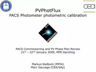
PolKa a tunable polarimeter for (sub)mm bolometer arrays. Giorgio Siringo Bolometer Development Millimeter & Submillimeter Astronomy Group Max-Planck-Institut für Radioastronomie (MPIfR) gsiringo@mpifr-bonn.mpg.de http://www.mpifr-bonn.mpg.de/staff/gsiringo/polka/polka.html

E N D
PolKaa tunable polarimeter for (sub)mm bolometer arrays Giorgio Siringo Bolometer Development Millimeter & Submillimeter Astronomy Group Max-Planck-Institut für Radioastronomie (MPIfR) gsiringo@mpifr-bonn.mpg.de http://www.mpifr-bonn.mpg.de/staff/gsiringo/polka/polka.html BPol Workshop - October 25-27, 2006 PolKa = Polarimeter für Bolometer Kameras
PolKaa tunable polarimeter for (sub)mm bolometer arrays PolKa team Giorgio Siringo Ernst Kreysa Lothar A. Reichertz Collaboration Giuseppe Cimò Thomas Krichbaum IPHT, Jena Bolometer Development Group @ MPIfR Walter Esch Hans-Peter Gemünd Ernst Kreysa (group leader) Gundula Lundershausen Giorgio Siringo PolKa = Polarimeter für Bolometer Kameras
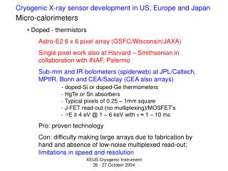
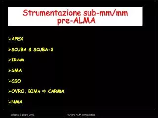
HUMBA: Hundred Millikelvin Bolometer Array (discontinued) • 19 NTD bolos, DC biased, AC coupled, • l = 2 mm (150 GHz), 100 mK (dilution fridge) • Used at the HHT and IRAM 30 m to observe SZ effect • HHT 19-channel Array: (discontinued) • 19 NTD bolos, DC biased, AC coupled • l = 850 mm (350 GHz) , 300 mK • Facility instrument at the Heinrich Hertz Telescope (HHT) • SIMBA: SEST Imaging Bolometer Array(discontinued) • 37 NTD bolos, DC biased, AC coupled + 5 AC biased and DC coupled • l = 1.2 mm (250 GHz) , 300 mK • Used in fast scanning without chopping secondary • Facility instrument at the Swedish-ESO Submillimeter Telescope (SEST) MPIfR Bolometer Arrays
MAMBO (Max-Planck Millimeter Bolometer) • NTD bolos, DC biased, AC coupled, l = 1.2 mm (250 GHz) , 300 mK • MAMBO-1: 37 elements • MAMBO-2: 117 elements • Facility instruments on the IRAM 30 m telescope, Pico Veleta, Spain • LABOCA (Large APEX Bolometer Camera) • 295 NTD bolos, AC biased, DC coupled, l = 850 mm (350 GHz) , 300 mK • Facility instrument on the APEX telescope (Atacama Pathfinder Experiment, Llano de Chajnantor, Chile) • SABOCA (Submillimeter APEX Bolometer Camera) • 37 TES bolos + SQUIDs multiplexing and amplification • = 350 mm (860 GHz) , 300 mK To be installed as facility instrument on the APEX telescope in early 2007 • LABOCA-2 (Large APEX Bolometer Camera) • 288 TES bolos + SQUIDs multiplexing and amplification • Will replace LABOCA at the end of 2007 • TES development in collaboration with IPHT (Institute for Physical High Technology) of Jena MPIfR Bolometer Arrays
LABOCA-2 Wafer(IPHT, Jena) 288 TES bolometers with integrated SQUIDs on a 4-inch wafer
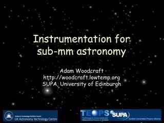
Polarimeter using a half-wave plate (HWP) • modulation: a rotating half-wave plate • analyzer: a fixed wire-grid polarizer • demodulation: a lock-in amplifier
Polarimeter using a HWP analyzer horizontal analyzer vertical • The modulation frequency is four times the mechanical one • Unpolarized radiation is not modulated (in theory…)
The PolKa polarimeter • PolKa is designed to be used with any of the MPIfR bolometer arrays (large diameter, wide range of wavelengths) • It uses a reflection-type HWP to modulate the polarization (crystal-type have stronger absorption and it is difficult to produce large diameters) • The HWP isrotated continuously by a precision motorized air-bearing: no chopping secondary mirror • Raw data (not demodulated) are acquired (fast data acquisition) • Demodulation made offline via a “software lock-in” algorithm
polarizer mirror The reflection-type HWP (RHWP) The RHWP is made of two parts: • a wire-grid polarizer • a flat metallic mirror By tuning the distance t between the two parts it is possible to produce a 180° phase shift between the two components of polarization for any operating wavelength This device uses metallic reflections and absorption is negligible
polarizer mirror The reflection-type HWP (RHWP) but: • large wire-grid polarizers are needed • they are produced only in a few labs in the world • have very long delivery time (order of years) • are expensive (in the range 103 - 105 $) We decided to produce them in our labs
Wire-grid production • ~4000 tungsten wires • wire size: 20 mm • step: 63 mm • position error: ~ 15 mm rms • clear aperture: 246 mm • market price: ~ 10,000 $
At the telescope Heinrich Hertz submillimeter Telescope (HHT), Mount Graham, ~120 Km north-east of Tucson, Arizona 3,186 m above the see level diameter: 10 m surface accuracy: 15 mm rms
At the telescope • the 246 mm version of PolKa was tested at the HHT on Jan 2002 • receiver: MPIfR 19 channel array@850 mm • rotation frequency: 3.5 Hz • polarization modulation: 14 Hz • full size HWP: full 19 channel array on the sky • improved analyzer system and... we had excellent weather!
At the telescope Observing modes We had two main observational strategies: • Polarization On-Off: to perform polarized flux measurements or detection experiments. Used on point sources. NEFD ~ 1650 mJy t(1/2) /(20” beam) • Polarization On-the-Fly maps: to map the polarization pattern of extended sources. NEFD ~ 380 mJy/(20” beam) per coverage (6’x6’, t~0.5 h) complemented by • Total power measurements: to get I and for point, focus, skydip
Polarization OO results an example: 3C279 OO data NOT demodulated AC coupling The signal is strong enough to be fitted using a sine!
Polarization OO results Linear polarization was detected on the two quasars 3C279 and 1633+382
Ori OMC-1 Coppin & al., A&A 356 (2000) Polarization OtF results A comparison: SCUBA-Pol • SCUBA-Pol @ JCMT: • 4092 m above the see level • 15 m telescope • 850 mm • Crystal type HWP • Step & integrate + wobbler • PolKa @ HHT: • 3186 m above the see level • 10 m telescope • 850 mm • Reflection type HWP • Continuous spinning & no wobbler SCUBA-Pol map Length = pol. degree Vectors rotated by 90°
Length = pol. degree Vectors rotated by 90° 12 maps co-added: ~ 6 h pol. degree map Coppin & al., A&A 356 (2000) Siringo & al., A&A 422 (2004)
SCUBA-Pol / ~7 h int.time Orion OMC-3 MMS3-4 PolKa map / 1.5 h int. time (3 scans) pol.intensity map B.C.Matthews & al., ApJ, 562 (2001)
Contours = CO(6-5) Grey-scale = 1.2 mm continuum IRAS 05358+3543 H.Beuther & al., A&A, 387 (2002) pol. degree map ~ 3 h int. time (6 scans)
Summary • We proposed a new concept of polarimeter for mm/submm wavelengths: RHWP + continuous spinning - wobbler • Results: • polarization detection on 3C279 and 1633+382 • polarization variability of 3C279 • high resolution polarization maps of Orion OMC-1, MMS3/4 in Orion OMC-3, IRAS 05358+3543 • The good points of PolKa are: • tunable over a wide range of wavelengths • low insertion loss (RHWP) • easy changeover between polarimetry and photometry • high modulation efficiency • high imaging quality (no chopping mirror) • These results confirm that the new concept is valid
We have 2 new RHWP units for our active experiments: • MAMBO-1 on the IRAM 30m telescope • Pico Veleta, Spain (3000 m amsl) • larger telescope: 30 m dish • longer wavelength: receiver MAMBO-1@ 1.2 mm • more sensitivity: MAMBO-1 has 37 bolometers • higher resolution: 11” beam • LABOCA on APEX • better site: Llano de Chajnantor, Chile (5,100 m amsl) • submillimeter telescope: 12 m dish, 15 mm rms • wavelength: 850mm • large array: 295 bolometers • high resolution: 18” beam • larger array: 11’ • fast mapping speed: 2’/s • higher sensitivity: 1 square degree in 1.5 hour, 125 mJy rms noise level Ongoing experiments
Contributions to BPol from ground based polarimeters: • Foreground observations (dust) • Instrument calibrations • Complications: • Small angular scale • Limitations due to the atmosphere • Available ground based polarimeters with bolometers: • QUaD, South Pole (optimized for CMB), 100-150 GHz • PolKa + MAMBO-1, Pico Veleta, Spain, 250 GHz • PolKa + LABOCA, APEX, Chile, 350 GHz • SHARP + SHARC-II, CSO, Hawaii, 860 GHz Hints for discussion
PolKaa tunable polarimeter for (sub)mm bolometer arrays Giorgio Siringo Bolometer Development Millimeter & Submillimeter Astronomy Group Max-Planck-Institut für Radioastronomie (MPIfR) gsiringo@mpifr-bonn.mpg.de http://www.mpifr-bonn.mpg.de/staff/gsiringo/polka/polka.html BPol Workshop - October 25-27, 2006 PolKa = Polarimeter für Bolometer Kameras