Download
1 / 10
100 likes | 302 Views
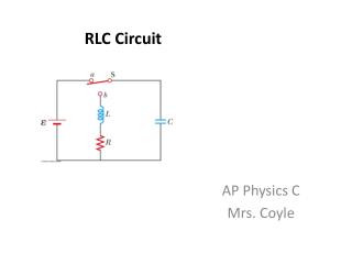
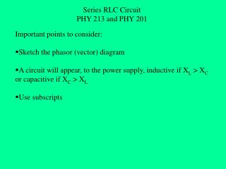
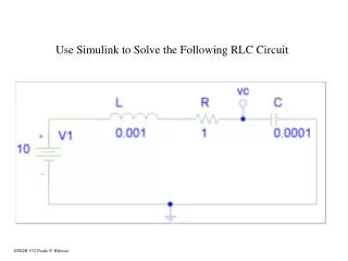
The RLC Circuit. AP Physics C Montwood High School R. Casao. A more realistic circuit consists of an inductor, a capacitor, and a resistor connected in series. Assume that the capacitor has an initial charge Qm before the switch is closed.

E N D
The RLC Circuit AP Physics C Montwood High School R. Casao
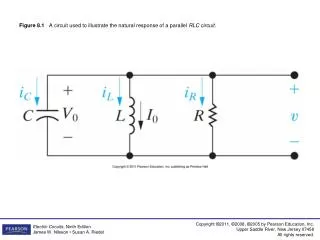
A more realistic circuit consists of an inductor, a capacitor, and a resistor connected in series. • Assume that the capacitor has an initial charge Qm before the switch is closed. • Once the switch is closed and a current is established, the total energy stored in the circuit at any time is given by:
The energy stored in the capacitor is and the energy stored in the inductor is 0.5·L·I2. • However, the total energy is no longer constant, as it was in the LC circuit, because of the presence of the resistor, which dissipates energy as heat. • Since the rate of energy dissipation through the resistor is I2·R, we have: • the negative sign signifies that U is decreasing in time.
Substituting this equation into the time derivative of the total energy stored in the LC circuit equation:
Factor out an I and set up the resulting quadratic equation:
The RLC circuit is analogous to the damped harmonic oscillator. • The equation of motion for the damped harmonic oscillator is: • Comparing the two equations: • Q corresponds to x; L corresponds to m; R corresponds to the damping constant b; and 1/C corresponds to 1/k, where k is the force constant of the spring. • The quantitative solution for the quadratic equation involves more knowledge of differential equations than we possess, so we will stick with the qualitative description of the circuit behavior.
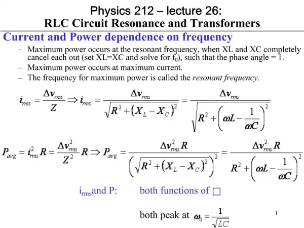
When R = 0 , reduces to a simple LC circuit and the charge and current oscillate sinusoidally in time. • When R is small, the solution is: • The charge will oscillate with damped harmonic motion in analogy with a mass-spring system moving in a viscous medium.
The graph of charge vs. time for a damped RLC circuit. • For large values of R, the oscillations damp out more rapidly; in fact, there is a critical resistance value Rc above which no oscillations occur. • The critical value is given by
A system with R = Rc is said to be critically damped. • When R exceeds Rc, the system is said to be overdamped. • The graph of Q vs. t for an overdamped RLC circuit, which occurs when the value of