1 / 3

Troubleshooting Ni/SiO2/HfO2 Backside Removal for Improved TEM Images

Addressing challenges in removing Ni/SiO2/HfO2 layers to enhance TEM imaging quality. Solutions involve dry Ni-InGaAs bonding, protecting Ni with HSQ, and using thicker Ni layers.

ronli
Download Presentation

Troubleshooting Ni/SiO2/HfO2 Backside Removal for Improved TEM Images

An Image/Link below is provided (as is) to download presentation Download Policy: Content on the Website is provided to you AS IS for your information and personal use and may not be sold / licensed / shared on other websites without getting consent from its author. Content is provided to you AS IS for your information and personal use only. Download presentation by click this link. While downloading, if for some reason you are not able to download a presentation, the publisher may have deleted the file from their server. During download, if you can't get a presentation, the file might be deleted by the publisher.

E N D

Presentation Transcript


  1. JustAfterCl-ICP

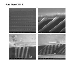
  2. AfterHFetch,and250’C2.5hanneal Lessmembranesupporting,somelineswrapandbreak Insomearea,theNiwastotallyremoved

  3. Tworemainingproblems: TheNi/SiO2/HfO2fromthebacksideisnotsoeasytobefullyremoved,andIcouldnotgetreproduciblegoodTEMimages. TheNilinesontopoftheNiareattachedbytheCl-ICPetch. PossibleSolutions: Dry the Ni-InGaAs bonding again with the small-window TEM grid, as well as thinner Ni layer that will not react all through the 50nm InGaAs. Writing the fins with HSQ fully cover the Ni to protect it, and use thicker Ni (200 nm).

More Related