Download
1 / 77
770 likes | 892 Views
This course, led by Instructor Andrea Goldsmith at Stanford University, delves into multiuser wireless systems and networks, covering topics such as future wireless networks, multiuser channels, spectral reuse, and various networking types including Ad-Hoc and cognitive radio networks. Students will engage with projects, paper presentations, and collaboration to deepen their understanding of wireless communications. With a focus on channel assignment and capacity challenges, this course prepares learners for advancements in ubiquitous communication technologies.

E N D
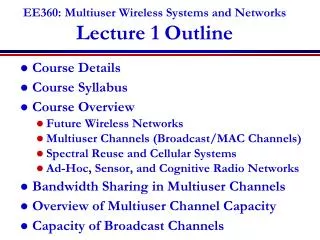
EE360: Multiuser Wireless Systems and NetworksLecture 1 Outline • Course Details • Course Syllabus • Course Overview • Future Wireless Networks • Multiuser Channels (Broadcast/MAC Channels) • Spectral Reuse and Cellular Systems • Ad-Hoc, Sensor, and Cognitive Radio Networks • Bandwidth Sharing in Multiuser Channels • Overview of Multiuser Channel Capacity • Capacity of Broadcast Channels
Course Information* People • Instructor: Andrea Goldsmith, andrea@ee, Packard 371, 5-6932, OHs: MW after class and by appt. • TA: Mainak Chowdhury, Email: mainakch@stanford.edu OHs: around HWs. Possibly around paper discussions organized via Piazza. • Class Administrator: Pat Oshiro, poshiro@stanford, Packard 365, 3-2681. *See web or handout for more details
Course InformationNuts and Bolts • Prerequisites: EE359 • Course Time and Location: MW 9:30-10:45. Y2E2 101. • Class Homepage: www.stanford.edu/class/ee360 • Contains all required reading, handouts, announcements, HWs, etc. • Class Mailing List: ee360win01314-students (automatic for on-campus registered students). • Guest list: send TA email to sign up • Tentative Grading Policy: • 10% Class participation • 10% Class presentation • 15% Homeworks • 15% Paper summaries • 50% Project (10% prop, 15% progress report, 25% final report+poster)
Grade Components • Class participation • Read the required reading before lecture/discuss in class • Class presentation • Present a paper related to one of the course topics • HW 0: Choose 3 possible high-impact papers, each on a different syllabus topic, by Jan. 13. Include a paragraph for each describing main idea(s), why interesting/high impact • Presentations begin Jan. 22. • HW assignments • Two assignments from book or other problems • Paper summaries • Two 2-4 page summaries of several articles • Each should be on a different topic from the syllabus
Project • Term project on anything related to multiuser wireless • Analysis, simulation and/or experiment • Must contain some original research • 2 can collaborate if project merits collaboration (scope, synergy) • Must set up website for project • Will post proposal, progress report, and final report to website • Project proposal due Jan. 27 at midnight • 1-2 page proposal with detailed description of project plan • Comments Feb 3, revised project proposal due Feb 10. • Progress report: due Feb. 24 at midnight • 2-3 page report with introduction of problem being investigated, system description, progress to date, statement of remaining work • Poster presentations last week of classes (We 3/13, Th 3/14?) • Final report due March 17 at midnight See website for details
Tentative Syllabus Weeks 1-2: Multiuser systems (Chapters 13.4 and 14, additional papers) Weeks 3-4: Cellular systems (Chapter 15, additional papers) Weeks 5-6: Ad hoc wireless networks (Chapter 16, additional papers) Week 7-8: Cognitive radio networks (papers) Week 8-9: Sensor networks (papers) Weeks 10: Additional Topics. Course Summary
Future Wireless Networks Ubiquitous Communication Among People and Devices Next-generation Cellular Wireless Internet Access Wireless Multimedia Sensor Networks Smart Homes/Spaces Automated Highways In-Body Networks All this and more …
Uplink (Multiple Access Channel or MAC): Many Transmitters to One Receiver. Downlink (Broadcast Channel or BC): One Transmitter to Many Receivers. x x x x h1(t) h21(t) h22(t) h3(t) Multiuser Channels:Uplink and Downlink R3 R2 R1 Challenge: How to share the channel among multiuser users Uplink and Downlink typically duplexed in time or frequency
BS Spectral Reuse In licensed bands and unlicensed bands Wifi, BT, UWB,… Cellular, Wimax Reuse introduces interference Due to its scarcity, spectrum is reused
Interference: Friend or Foe? Increases BER Reduces capacity • If treated as noise: Foe • If decodable (MUD): Neither friend nor foe • If exploited via cooperation and cognition: Friend (especially in a network setting)
BASE STATION Cellular Systems Reuse channels to maximize capacity • 1G: Analog systems, large frequency reuse, large cells, uniform standard • 2G: Digital systems, less reuse (1 for CDMA), smaller cells, multiple standards, evolved to support voice and data (IS-54, IS-95, GSM) • 3G: Digital systems, WCDMA competing with GSM evolution. • 4G: OFDM/MIMO • 5G: ??? MTSO
Rethinking “Cells” in Cellular How should cellular systems be designed? • Traditional cellular design “interference-limited” • MIMO/multiuser detection can remove interference • Cooperating BSs form a MIMO array: what is a cell? • Relays change cell shape and boundaries • Distributed antennas move BS towards cell boundary • Small cells create a cell within a cell • Mobile cooperation via relaying, virtual MIMO, analog network coding. Coop MIMO Small Cell Relay Will gains in practice be big or incremental; in capacity or coverage? DAS
Ad-Hoc/Mesh Networks ce Outdoor Mesh Indoor Mesh
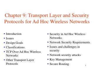
Ad-Hoc Networks • Peer-to-peer communications • No backbone infrastructure or centralized control • Routing can be multihop. • Topology is dynamic. • Fully connected with different link SINRs • Open questions • Fundamental capacity • Optimal routing • Resource allocation (power, rate, spectrum, etc.)
Design Issues • Ad-hoc networks provide a flexible network infrastructure for many emerging applications. • The capacity of such networks is generally unknown. • Transmission, access, and routing strategies for ad-hoc networks are generally ad-hoc. • Crosslayer design critical and very challenging. • Energy constraints impose interesting design tradeoffs for communication and networking.
Cognition Radios • Cognitive radios can support new wireless users in existing crowded spectrum • Without degrading performance of existing users • Utilize advanced communication and signal processing techniques • Coupled with novel spectrum allocation policies • Technology could • Revolutionize the way spectrum is allocated worldwide • Provide sufficient bandwidth to support higher quality and higher data rate products and services
Cognitive Radio Paradigms Knowledge and Complexity • Underlay • Cognitive radios constrained to cause minimal interference to noncognitive radios • Interweave • Cognitive radios find and exploit spectral holes to avoid interfering with noncognitive radios • Overlay • Cognitive radios overhear and enhance noncognitive radio transmissions
Underlay Systems IP NCR CR CR NCR • Cognitive radios determine the interference their transmission causes to noncognitive nodes • Transmit if interference below a given threshold • The interference constraint may be met • Via wideband signalling to maintain interference below the noise floor (spread spectrum or UWB) • Via multiple antennas and beamforming
Interweave Systems • Measurements indicate that even crowded spectrum is not used across all time, space, and frequencies • Original motivation for “cognitive” radios (Mitola’00) • These holes can be used for communication • Interweave CRs periodically monitor spectrum for holes • Hole location must be agreed upon between TX and RX • Hole is then used for opportunistic communication with minimal interference to noncognitive users
Overlay Systems RX1 CR RX2 NCR • Cognitive user has knowledge of other user’s message and/or encoding strategy • Used to help noncognitive transmission • Used to presubtract noncognitive interference
Wireless Sensor and “Green” Networks • Smart homes/buildings • Smart structures • Search and rescue • Homeland security • Event detection • Battlefield surveillance • Energy (transmit and processing) is driving constraint • Data flows to centralized location (joint compression) • Low per-node rates but tens to thousands of nodes • Intelligence is in the network rather than in the devices • Similar ideas can be used to re-architect systems and networks to be green
Energy-Constrained Nodes • Each node can only send a finite number of bits. • Transmit energy minimized by maximizing bit time • Circuit energy consumption increases with bit time • Introduces a delay versus energy tradeoff for each bit • Short-range networks must consider transmit, circuit, and processing energy. • Sophisticated techniques not necessarily energy-efficient. • Sleep modes save energy but complicate networking. • Changes everything about the network design: • Bit allocation must be optimized across all protocols. • Delay vs. throughput vs. node/network lifetime tradeoffs. • Optimization of node cooperation.
Green” Cellular Networks How should cellular systems be redesigned for minimum energy? • Minimize energy at both the mobile andbase station via • New Infrastuctures: cell size, BS placement, DAS, Picos, relays • New Protocols: Cell Zooming, Coop MIMO, RRM, Scheduling, Sleeping, Relaying • Low-Power (Green) Radios: Radio Architectures, Modulation, coding, MIMO Pico/Femto Coop MIMO Relay Research indicates that signicant savings is possible DAS
Crosslayer Design in Wireless Networks • Application • Network • Access • Link • Hardware Tradeoffs at all layers of the protocol stack are optimized with respect to end-to-end performance This performance is dictated by the application
Uplink (Multiple Access Channel or MAC): Many Transmitters to One Receiver. Downlink (Broadcast Channel or BC): One Transmitter to Many Receivers. x x x x h1(t) h21(t) h22(t) h3(t) Uplink and Downlink R3 R2 R1 Challenge: How to share the channel among multiuser users Uplink and Downlink typically duplexed in time or frequency
Random Access RANDOM ACCESS TECHNIQUES • Dedicated channels wasteful for data • Use statistical multiplexing • Techniques • ALOHA and slotted ALOHA • Carrier sensing • Collision detection or avoidance • Reservation protocols (similar to deterministic access) • Retransmissions used for corrupted data • Poor throughput and delay characteristics under heavy loading 7C29822.038-Cimini-9/97
.40 .30 Throughput per Packet Time) .20 .10 0 0.5 1.0 1.5 2.0 3.0 G (Attempts per Packet TIme) ALOHA Slotted Aloha Pure Aloha • Data is packetized • Retransmit • When packets collide • Pure ALOHA • send packet whenever data is available • a collision occurs for any partial overlap of packets • Slotted ALOHA • send packets during predefined timeslots • avoids partial overlap of packets • Comments • Inefficient for heavily loaded systems • Capture effect (packets with high SINR decoded) improves efficiency
Carrier Sense Techniques CTS RTS Busy Tone Wired Network Wireless Network • Channel sensed before transmission • To determine if it is occupied • More efficient than ALOHA fewer retransmissions • Carrier sensing is often combined with collision detection in wired networks (e.g. Ethernet) not possible in a radio environment • Collision avoidance (busy tone, RTS/CTS) can be used
Code Space Code Space Code Space Time Time Time Frequency Frequency Frequency Deterministic Bandwidth Sharing • Frequency Division • Time Division • Code Division • Multiuser Detection • Space Division (MIMO) • Hybrid Schemes What is optimal? Look to Shannon.
Multiple Access SS • Interference between users mitigated by code cross correlation • In downlink, signal and interference have same received power • In uplink, “close” users drown out “far” users (near-far problem) a a
Multiuser Detection • In all CDMA systems and in TD/FD/CD cellular systems, users interfere with each other. • In most of these systems the interference is treated as noise. • Systems become interference-limited • Often uses complex mechanisms to minimize impact of interference (power control, smart antennas, etc.) • Multiuser detection exploits the fact that the structure of the interference is known • Interference can be detected and subtracted out • Better have a darn good estimate of the interference
Ideal Multiuser Detection - Signal 1 = Signal 1 Demod Iterative Multiuser Detection A/D A/D A/D A/D Signal 2 Signal 2 Demod - = Why Not Ubiquitous Today? Power and A/D Precision
Multiuser Shannon CapacityFundamental Limit on Data Rates Capacity: The set of simultaneously achievable rates {R1,…,Rn} with arbitrarily small probability of error • Main drivers of channel capacity • Bandwidth and received SINR • Channel model (fading, ISI) • Channel knowledge and how it is used • Number of antennas at TX and RX • Duality connects capacity regions of uplink and downlink R3 R2 R3 R2 R1 R1
Broadcast Channel Capacity Region in AWGN • Model • One transmitter, two receivers with spectral noise density n1, n2: n1<n2. • Transmitter has average power Pand total bandwidth B. • Single User Capacity: • Maximum achievable rate with asymptotically small Pe • Set of achievable rates includes (C1,0) and (0,C2), obtained by allocating all resources to one user.
Rate Region: Time Division • Time Division (Constant Power) • Fraction of time t allocated to each user is varied • Time Division (Variable Power) • Fraction of time t and power siallocated to each user is varied
Rate Region: Frequency Division • Frequency Division • Bandwidth Biand power Siallocated to each user is varied. Equivalent to TD for Bi=tiB and Pi=tisi.
Superposition Coding Best user decodes fine points Worse user decodes coarse points
Code Division • Superposition Coding • Coding strategy allows better user to cancel out interference from worse user. • DS spread spectrum with spreading gain G and cross correlationr12= r21 =G: • By concavity of the log function, G=1 maximizes the rate region. • DS without interference cancellation
Broadcast: One Transmitter to Many Receivers. Wireless Gateway Multiple Access: Many Transmitters to One Receiver. x x x g1(t) g2(t) g3(t) Broadcast and MAC Fading Channels Wired Network R3 R2 R1 Goal: Maximize the rate region {R1,…,Rn}, subject to some minimum rate constraints, by dynamic allocation of power, rate, and coding/decoding. Assume transmit power constraint and perfect TX and RX CSI
Fading Capacity Definitions • Ergodic (Shannon) capacity: maximum long-term rates averaged over the fading process. • Shannon capacity applied directly to fading channels. • Delay depends on channel variations. • Transmission rate varies with channel quality. • Zero-outage (delay-limited*) capacity: maximum rate that can be maintained in all fading states. • Delay independent of channel variations. • Constant transmission rate – much power needed for deep fading. • Outage capacity: maximum rate that can be maintained in all nonoutage fading states. • Constant transmission rate during nonoutage • Outage avoids power penalty in deep fades *Hanly/Tse, IT, 11/98
+ + + + Two-User Fading Broadcast Channel h1[i] n1[i] Y1[i] x X[i] Y2[i] x n2[i] h2[i] At each time i: n={n1[i],n2[i]} n1[i]=n1[i]/h1[i] Y1[i] X[i] Y2[i] n2[i]=n2[i]/h2[i]
Ergodic Capacity Region* • Capacity region: ,where • The power constraint implies • Superposition coding and successive decoding achieve capacity • Best user in each state decoded last • Power and rate adapted using multiuser water-filling: power allocated based on noise levels and user priorities *Li/Goldsmith, IT, 3/01
Zero-Outage Capacity Region* • The set of rate vectors that can be maintained for all channel states under power constraint P • Capacity region defined implicitly relative to power: • For a given rate vector R and fading state n we find the minimum power Pmin(R,n) that supports R. • RCzero(P) if En[Pmin(R,n)] P *Li and Goldsmith, IT, 3/01
Outage Capacity Region • Two different assumptions about outage: • All users turned off simultaneously (common outage Pr) • Users turned off independently (outage probability vector Pr) • Outage capacity region implicitly defined from the minimum outage probability associated with a given rate • Common outage: given (R,n), use threshold policy • IfPmin(R,n)>s* declare an outage, otherwise assign this power to state n. • Power constraint dictates s* : • Outage probability:
Independent Outage • With independent outage cannot use the threshold approach: • Any subset of users can be active in each fading state. • Power allocation must determine how much power to allocate to each state and which users are on in that state. • Optimal power allocation maximizes the reward for transmitting to a given subset of users for each fading state • Reward based on user priorities and outage probabilities. • An iterative technique is used to maximize this reward. • Solution is a generalized threshold-decision rule.
Minimum-Rate Capacity Region • Combines ergodic and zero-outage capacity: • Minimum rate vector maintained in all fading states. • Average rate in excess of the minimum is maximized. • Delay-constrained data transmitted at the minimum rate at all times. • Channel variation exploited by transmitting other data at the maximum excess average rate.
Minimum Rate Constraints • Define minimum rates R* = (R*1,…,R*M): • These rates must be maintained in all fading states. • For a given channel state n: • R* must be in zero-outage capacity region • Allocate excess power to maximize excess ergodic rate • The smaller R*, the bigger the min-rate capacity region
Comparison of Capacity Regions • For R* far from Czero boundary, Cmin-rateCergodic • For R* close to Czero boundary, Cmin-rateCzeroR*