Download
1 / 55
550 likes | 800 Views
This chapter discusses the differences between two types of network switching - circuit-switched and datagram networks - and explores a hybrid approach, virtual-circuit networks. It covers topics such as efficiency, delay, and addressing.

E N D
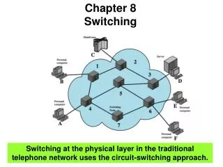
Chapter 8 Switching
Switching • Switching • Switches are devices capable of creating temporary connections between two or more devices linked to the switch.
Switching Figure 8.2 Taxonomy of switched networks
8-1 CIRCUIT-SWITCHED NETWORKS A circuit-switched network consists of a set of switches connected by physical links. A connection between two stations is a dedicated path made of one or more links. However, each connection uses only one dedicated channel on each link. Each link is normally divided into n channels by using FDM or TDM. Topics discussed in this section: Three PhasesEfficiencyDelay Circuit-Switched Technology in Telephone Networks
A trivial circuit-switched network • When end system A needs to communicate with sys. M • Setup Phase ; System A needs to request a connection to M that must be accepted by all switches as well as by M itself. • A channel is reserved on each link, and the combination of channels defines the dedicated path. • Data transfer ; After the dedicated path made of connected channels is established, data transfer can take place. • Teardown Phase ; After all data have been transferred, the circuits are torn down.
Note In circuit switching, the resources need to be reserved during the setup phase;the resources remain dedicated for the entire duration of data transfer until the teardown phase.
Efficiency & delay • Efficiency • Circuit switched networks are not as efficient as the other two types of networks because resources are allocated during the entire duration of the connection. • These resources are unavailable to other connections. • Delay • Although a circuit-switched network normally has low efficiency, the delay in this type of network is minimal. • During data transfer the data are not delayed at each switch; the resources are allocated for the duration of the connection.
Note Switching at the physical layer in the traditional telephone network uses the circuit-switching approach.
8-2 DATAGRAM NETWORKS In data communications, we need to send messages from one end system to another. If the message is going to pass through a packet-switched network, it needs to be divided into packets of fixed or variable size. The size of the packet is determined by the network and the governing protocol. Topics discussed in this section: Routing TableEfficiencyDelay Datagram Networks in the Internet
Note In a packet-switched network, there is no resource reservation; resources are allocated on demand.
Datagram network • In datagram network, each packet is treated independently of all others. • Even if a packet is part of a multipacket transmission, the network treats it as though it existed alone. Figure 8.7 A datagram network with four switches (router)
Routing table Figure 8.8 Routing table in a datagram network A switch in a datagram network uses a routing table that is based on the destination address.
Note The destination address in the header of a packet in a datagram network remains the same during the entire journey of the packet. The efficiency of a datagram network is better than that of a circuit-switched network; resources are allocated only when there are packets to be transferred.
Delay • There may be greater delay in a datagram network than in a virtual-circuit network. • Total delay = 3T + 3זּ+ w1 + w2 Where, T=Transmission time, זּ=Propagation delay, w=Waiting time Figure 8.9 Delay in a datagram network
Note Switching in the Internet is done by using the datagram approach to packet switching at the network layer.
8-3 VIRTUAL-CIRCUIT NETWORKS A virtual-circuit network is a cross between a circuit-switched network and a datagram network. It has some characteristics of both. Topics discussed in this section: AddressingThree Phases EfficiencyDelay Circuit-Switched Technology in WANs
Virtual-Circuit Network • Characteristics of Virtual-circuit network • As in a circuit-switched network, there are setup and teardown phases in addition to the data transfer phase. • Resources can be allocated during the setup phase, as in a circuit -switched network, or on demand, as in a datagram network. • As in a datagram network, data are packetized and each packet carries an address (local jurisdiction) in the header. • As in a circuit network, all packets follow the same path established during the connection. • A virtual-circuit network is normally implemented in the data link layer, while a circuit-switched network is implemented in the physical layer and a datagram network in the network layer.
Virtual-Circuit Network • The virtual-circuit network has switches that allow traffic from sources to destinations. • A source or destination can be a computer, packet switch, or other device that connects other network. Figure 8.10 Virtual-circuit network
Global Addressing • In virtual circuit networks, • A global address that can be unique in the scope of the WAN or international network. • global addressing in virtual circuit networks is used only to create a virtual circuit identifier.
Virtual Circuit Identifier (VCI) • VCI is actually used for data transfer. • VCI (Virtual Circuit Identifier) • is a small number that only has switch scope, • it is used by a frame between two switches. • Each switch can use its own unique set of VCIs
Three Phases • To communicate, a source and destination need to go through three phases • setup, data transfer, teardown
Three Phases • In the setup phase, the source and destination use their global addresses to help switches make table entries for the connection. • In the teardown phase, the source and destination inform the switches to erase the corresponding entry. • Data phase occurs between these two phases.
Data Transfer Phase • To transfer a frame from a source to its destination, all switches need to have a table entry for this virtual circuit.
Data Transfer Phase (cont’d) • Source-to-destination data Transfer
Setup Phase • How does a switch create an entry for a virtual circuit? • Switched virtual circuit (SVC) approach • Suppose source A needs to create a virtual circuit to B. • Two steps are required; • the setup request and the acknowledgment.
Switched Virtual Circuit (SVC) • Creating temporary and short connection that exists only when data are being transferred between source and destination. • Setup request VCI (77) lets the destination know that the frames come from A and not other sources
SVC (cont’d) • SVC setup acknowledgment
Teardown Phase • In this phase, source A, after sending all frames to B, sends a special frame called a teardown request. • Destination B responds with a teardown confirmation frame. • All switches erase the corresponding entry from their tables.
Note Efficiency In virtual-circuit switching, all packets belonging to the same source and destination travel the same path; but the packets may arrive at the destination with different delays if resource allocation is on demand.
Delay in Virtual-circuit networks • There is a one-time delay for setup and a one-time delay for teardown. • If resources are allocated during the setup phase, there is no wait time for individual packets. • Total delay time = 3T + 3 זּ + setup delay + teardown time
Note Switching at the data link layer in a switched WAN is normally implemented by using virtual-circuit techniques.
8.4 STRUCTURE OF A SWITCH We use switches in circuit-switched and packet-switched networks. In this section, we discuss the structures of the switches used in each type of network. Topics discussed in this section: Structure of Circuit SwitchesStructure of Packet Switches
Circuit Switching(cont’d) • Structure of Circuit Switching ~ can use either two technologies. • Switching
Circuit Switching(cont’d) • Space-Division Switches • the paths in the circuit are separated from each other spatially(crossbar switch) • Crossbar switch ~ connect n input to m output in a grid, using electronic microswitch(transistor) at each crosspoint.
Circuit Switching(cont’d) Figure 8.17 Crossbar switch with three inputs and four outputs
Circuit Switching(cont’d) • Limitation of crossbar switch • The number of switch (huge size) : connect n inputs by m output • require n * m crosspoint. (ex : 1000 input, 1000 output → 1,000,000 crosspoint) • inefficient • fewer than 25% of the crosspoints are in use at a given time. • the rest are idle
Circuit Switching(cont’d) • Multistage switch ~ combines crossbar switches in several (normally three) stages to solve the limitation of the crossbar switch. Figure 8.18 Multistage switch
Circuit Switching(cont’d) • Time-Division Switch • uses Time-division multiplexing (TDM) inside a switch. • The most popular technology is called the time-slot interchange (TSI). • TSI changes the ordering of the slots based on the desired connections.
Circuit Switching(cont’d) • Time-division multiplexing without a time-slot interchange(TSI)
Circuit Switching(cont’d) • Time-division multiplexing with a time-slot interchange(TSI)
Circuit Switching(cont’d) • TSI Figure 8.19 Time-slot interchange
Circuit Switching(cont’d) • Space-and Time-Division Switching Combinations ~ combine space-division and time-division technology to take advantage of the best of both • TST(time-space-time) • TSST(time-space-space-time) • STTS(space-time-time-space)
Circuit Switching(cont’d) Figure 8.20 Time-space-time switch
Structure of Packet switches • A switch used in a packet-switched network has a different structure from a switch used in a circuit-switched network. • A packet switch has four components; • input ports, output ports, the routing processor, and the switching fabric. Figure 8.21 Packet switch components
Structure of Packet switches Figure 8.22 Input port • An input port performs the physical and data link functions of the packet switch.
Structure of Packet switches Figure 8.23 Output port • An output port performs the same functions as the input port, but in the reverse order.
Structure of Packet switches • Routing Processor • The routing processor performs of the network layer. • Switching fabrics • The most difficult task in a packet switch is to move the packet from the input queue to the output queue. • Today, packet switches are specialized mechanisms that use a variety of switching fabrics. • Crossbar switch : Simplest type of switching fabric is the crossbar switch.
Structure of Packet switches Figure 8.24 A banyan switch • A banyan switch is a multistage switch with microswitches at each stage that route the packets based on the output port represented as a binary string.