Overview of Switched Networks and Their Phases
Learn about circuit-switched networks, datagram networks, and virtual-circuit networks, including their components, efficiency, delays, and technologies used.

Overview of Switched Networks and Their Phases
E N D
Presentation Transcript
Chapter 3 Switching
Switched network 2/31
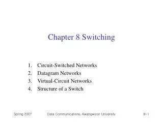
CIRCUIT-SWITCHED NETWORKS A circuit-switched network consists of a set of switches connected by physical links. A connection between two stations is a dedicated path made of one or more links. However, each connection uses only one dedicated channel on each link. Each link is normally divided into n channels by using FDM or TDM. Topics discussed in this section: Three PhasesEfficiencyDelay Circuit-Switched Technology in Telephone Networks
Note A circuit-switched network is made of a set of switches connected by physical links, in which each link is divided into n channels.
Note In circuit switching, the resources need to be reserved during the setup phase;the resources remain dedicated for the entire duration of data transfer until the teardown phase.
Example As a trivial example, let us use a circuit-switched network to connect eight telephones in a small area. Communication is through 4-kHz voice channels. We assume that each link uses FDM to connect a maximum of two voice channels. The bandwidth of each link is then 8 kHz. Next Figure shows the situation. Telephone 1 is connected to telephone 7; 2 to 5; 3 to 8; and 4 to 6. Of course the situation may change when new connections are made. The switch controls the connections.
Example As another example, consider a circuit-switched network that connects computers in two remote offices of a private company. The offices are connected using a T-1 line leased from a communication service provider. There are two 4 × 8 (4 inputs and 8 outputs) switches in this network. For each switch, four output ports are folded into the input ports to allow communication between computers in the same office. Four other output ports allow communication between the two offices. Next Figure shows the situation. 10/31
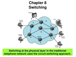
Note Switching at the physical layer in the traditional telephone network uses the circuit-switching approach.
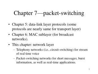
DATAGRAM NETWORKS In data communications, we need to send messages from one end system to another. If the message is going to pass through a packet-switched network, it needs to be divided into packets of fixed or variable size. The size of the packet is determined by the network and the governing protocol. Topics discussed in this section: Routing TableEfficiencyDelay Datagram Networks in the Internet 14/31
Note In a packet-switched network, there is no resource reservation; resources are allocated on demand. 15/31
Note A switch in a datagram network uses a routing table that is based on the destination address. 18/31
Note The destination address in the header of a packet in a datagram network remains the same during the entire journey of the packet. 19/31
Note Switching in the Internet is done by using the datagram approach to packet switching at the network layer. 21/31
VIRTUAL-CIRCUIT NETWORKS A virtual-circuit network is a cross between a circuit-switched network and a datagram network. It has some characteristics of both. Topics discussed in this section: AddressingThree Phases EfficiencyDelay Circuit-Switched Technology in WANs 22/31
Virtual-circuit network 23/31
Source-to-destination data transfer in a virtual-circuit network 26/31
Note In virtual-circuit switching, all packets belonging to the same source and destination travel the same path; but the packets may arrive at the destination with different delays if resource allocation is on demand. 29/31
Note Switching at the data link layer in a switched WAN is normally implemented by using virtual-circuit techniques. 31/31