Download
1 / 16
170 likes | 342 Views
Origins of Decoherence in Coherent X-ray Diffraction Experiments. I.A. Vartanyants , I.K. Robinson Department of Physics, UIUC, Urbana-Champaign,USA. Optics Communications (2003), 222 , 29-50. Optical Components on a Typical Beamline. Source. Double-Crystal Monochromator. Sample.

E N D
Origins of Decoherence in Coherent X-ray Diffraction Experiments I.A. Vartanyants, I.K. Robinson Department of Physics, UIUC, Urbana-Champaign,USA Optics Communications (2003), 222, 29-50.
Optical Components on a Typical Beamline Source Double-Crystal Monochromator Sample Be window Slits Slits How coherent properties of the beam are changed passing through all this elements?
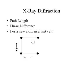
Laws of Propagation of Mutual Coherence Function Mutual Coherence Function: Γ(P1,P2;τ)=<E(P1,t+ τ)E*(P2,t)>T Mutual Intensity Function: J(P1,P2 )=Γ(P1,P2;0)= <E(P1,t)E*(P2,t)>T P1 R1 Q1 n1 Q2 P2 R2 n2 Σ1 Σ2 Propagation of MIF: Complex Coherence Factor:
Propagation of MIF through the Optical Element Be window Sample Source R1 R2 s r u L1 L2 MIF at sample position: Green’s function: (propagator) T(u) – amplitude transmittance function
Limits of Coherent and Incoherent Illumination Coherent illumination Incoherent illumination generalized van Cittert-Zernike theorem
Transmittance Function Complex transmittance function Be window d(u) Mirror h(u)
Propagation of MIF through a random OE • Assumptions: • Optical element (Be window, mirror) considered as a random optical element • Partial coherent incoming beam • in<<eff –transverse coherence length of the incoming beam is smaller then the intensity distribution MIF passing such random OE: autocorrelation function
Autocorrelation function for random phase object • Assumptions: • Gaussian statistics • Stationary random process varience normalized phase autocorrelation Autocorrelation function where
Propagation of MIF through a random OE Undistorted part: van Cittert-Zernike theorem: Rescattered part:
Propagation of MIF through a random OE Source (σsx, σsy) Sample JS(r1,r2) Be window (σwx, σwy) JW(r1,r2) L1 L2
Parameters used for calculation of <J( r)> Table II Transverse coherence lengths of the ‘broad’ sand ‘sharp’ wcomponents of MIF <J(r)> on sample position Table I Parameters used for calculation of the CCF (r) x,y-horizontal and vertical source sizes, (eff)-effective source size of the beam on Be window, 2 and -varience and longitudinal correlation length Letters (L) and (G) mean Lorentzian or Gaussian form of CCF W(r).
Imaging of small crystals Diffracted intensity (partial coherent illumination): projection of shape function of particle s(r,z) MIF at sample position: Coherent illumination |<(r)>|=1
Iterative phase retrieval algorithm FFT sk(x) Ak(q) Real Space Constraints Reciprocal Space Constraints s'k(x) A'k(q) FFT-1 • Real space constraints: • finite support • real, positive Reciprocal space constraint: R.W.Gerchberg & W.O. Saxton, Optic (1972) 35, 237 J.R. Fienup, Appl Opt. (1982). 21, 2758 R.P. Millane & W.J. Stroud, J. Opt. Soc. Am. (1997) A14, 568
Imaging of small crystals(partial coherent illumination) MIF <J(r)> on sample position diffracted intensity I(Q) reconstructed crystal images for two different sets of random phases
Conclusions • Optical elements in the beamline can change coherence properties of the beam • MIF in the incoming beam (on the sample position) can be multicomponent function due to propagation through different optical elements (windows and mirrors) • Partial coherence of incoming beam can introduce an artifacts in reconstructed images of nanoparticles