Download
1 / 29
290 likes | 410 Views
This paper discusses the development of a low-cost concurrent error detection (CED) scheme specifically tailored for finite state machines (FSMs) implemented using embedded memory blocks in FPGAs. Traditional techniques designed for gate and flip-flop implementations do not account for the unique vulnerabilities of SRAM-based configurations, which can be more susceptible to transient faults. The paper outlines the architecture of the proposed CED scheme, evaluates its effectiveness in fault detection, and assesses the overhead involved in its implementation. Key applications and examples of typical FPGA architectures are also provided to illustrate the approach.

E N D
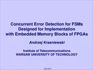
Concurrent Error Detection for FSMs Designed for Implementation with Embedded Memory Blocks of FPGAs Andrzej Krasniewski Institute of Telecommunications WARSAW UNIVERSITY OF TECHNOLOGY DSD 2007
Earlier proposed techniques, intended for FSMs implemented with gates and FFs (standard cells) - unsuitable GOAL Develop a low-cost CED scheme for FSMs implemented using embedded memory of FPGAs Motivation Why CED for FSMs implemented with SRAM-based FPGAs? • configuration memory - susceptible to transient faults • embedded memory (major component of FSMs) - more susceptible to transient faults than logic • architectural features of FPGAs with embedded memory make CED relatively inexpensive
OUTLINE • Implementation of FSMs using FPGAs with embedded memory • Concurrent error detection • - architecture • - effectiveness of fault detection • - overhead • Conclusion
OUTLINE • Implementation of FSMs using FPGAs with embedded memory • Concurrent error detection • - architecture • - effectiveness of fault detection • - overhead • Conclusion
Embedded memory in FPGAs - Example Altera Stratix M512 RAM block M4K RAM block IOEs IOEs IOEs IOEs IOEs IOEs LABs LABs LABs LABs LABs LABs IOEs LABs LABs LABs LABs LABs LABs IOEs LABs LABs LABs LABs IOEs LABs LABs LABs LABs IOEs LABs LABs LABs LABs M-RAM block IOEs LABs LABs LABs LABs IOEs LABs LABs LABs LABs IOEs LABs LABs LABs LABs IOEs LABs LABs LABs LABs IOEs LABs LABs LABs LABs IOEs LABs LABs LABs LABs DSP block
read-only memory modules (ROMs) • implementation of combinational logic • implementation of sequential logic (FSMs) Embedded memory in FPGAs - Applications • read/write memory modules • RAM • FIFO • shift registers
EXTENDED STRUCTURE input m p ADDRESS MODIFIER (gates) w < m+p ADDRESS REGISTER address w ROM n output next state limited applicability – requires large memory ROM-based FSM design SIMPLE STRUCTURE entire combinational logic located in memory (ROM) input m p ADDRESS REGISTER address m+p ROM n output next state
LUTs in PLBs (Xilinx CLBs, Altera LEs) flip-flops in PLBs (internal register of Emb Mem) Embedded Memory CED scheme in [DFT’04] FSM design for FPGA with embedded mem. input ADDRESS MODIFIER ADDRESS REGISTER address ROM output next state
studies in synthesis of FPGA-based circuits Embedded Memory new CED scheme FSM design for FPGA with embedded mem. input ADDRESS MODIFIER flip-flops in PLBs (internal register of Emb Mem) ADDRESS REGISTER address ROM Embedded Memory output next state
FSM design for FPGA with embedded mem. input X, next state Q group a → Addr Reg group b → Addr Reg & Mem G group c → Mem G input X Xb, Xc Qb, Qc ADDRESS MODIFIER embedded memory memory G Xa, Xb Qa, Qb programmable logic components ADDRESS REGISTER clock A1 A2 embedded memory memory H „ROM” next state Q output Y
OUTLINE • Implementation of FSMs using FPGAs with embedded memory • Concurrent error detection • - architecture • - effectiveness of fault detection • - overhead • Conclusion
one extra bit of address → size of the required memory doubles • address space of EMBs - quite limited (address 13 bits) • width of the embedded memory word can be extended significantly with no impact on the performance (speed) of the circuit state encoded with a minimal no. of bits earlier proposed CED techniques for sequential circuits (based on state encoding with EDC)- not applicable Assumptions input GOAL: low-cost solution memory G (ADDR MOD) • CEDscheme: • can add to the width of the mem. word • cannot add to the width of mem. address ADDR REG address memory H („ROM”) output next state
Proposed CED scheme INPUT pXab’ Xa Xb Xc pXc’ ADDRESS MODIFIER OUTPUT PARITY CHECKER A2 pA2’ pXQc ADDRESS REGISTER ERR3 pQab’ Xa Xb Qa Qb A2 pA2’ pXQc pXc’ pQc’ pXab’ clock A1 AUXILIARY CHECKER ERR2 ADDRESS PARITY CHECKER „ROM” ERR1 Qa+ Qb+ Qc+ pQab+’ pQc+’ Y pY pA L address A next state OUTPUT ERR4
Error detection mechanisms ERR1 parity checking for address to memory H ERR2 parity checking for data feeding memory G only ERR3 parity checking for output ERR4 checking for address legality (optional) Checkers implemented with PLBs (outputs – in two-rail code)
parity checking for address to memory H INPUT pXab’ Xa Xb Xc pXc’ ADDRESS MODIFIER OUTPUT PARITY CHECKER A2 pA2’ pXQc ADDRESS REGISTER ERR3 pQab’ Xa Xb Qa Qb A2 pA2’ pXQc pXc’ pQc’ pXab’ clock A1 AUXILIARY CHECKER ERR2 ADDRESS PARITY CHECKER „ROM” ERR1 Qa+ Qb+ Qc+ pQab+’ pQc+’ Y pY pA L address A next state OUTPUT ERR4
parity checking for data feeding memory G only INPUT pXab’ Xa Xb Xc pXc’ ADDRESS MODIFIER OUTPUT PARITY CHECKER A2 pA2’ pXQc ADDRESS REGISTER ERR3 pQab’ Xa Xb Qa Qb A2 pA2’ pXQc pXc’ pQc’ pXab’ clock A1 AUXILIARY CHECKER ERR2 ADDRESS PARITY CHECKER „ROM” ERR1 Qa+ Qb+ Qc+ pQab+’ pQc+’ Y pY pA L address A next state OUTPUT ERR4
parity checking for output INPUT pXab’ Xa Xb Xc pXc’ ADDRESS MODIFIER OUTPUT PARITY CHECKER A2 pA2’ pXQc ADDRESS REGISTER ERR3 pQab’ Xa Xb Qa Qb A2 pA2’ pXQc pXc’ pQc’ pXab’ clock A1 AUXILIARY CHECKER ERR2 ADDRESS PARITY CHECKER „ROM” ERR1 Qa+ Qb+ Qc+ pQab+’ pQc+’ Y pY pA L address A next state OUTPUT ERR4
checking for address legality INPUT pXab’ Xa Xb Xc pXc’ ADDRESS MODIFIER OUTPUT PARITY CHECKER A2 pA2’ pXQc ADDRESS REGISTER ERR3 pQab’ Xa Xb Qa Qb A2 pA2’ pXQc pXc’ pQc’ pXab’ clock A1 AUXILIARY CHECKER ERR2 ADDRESS PARITY CHECKER „ROM” ERR1 Qa+ Qb+ Qc+ pQab+’ pQc+’ Y pY pA L address A next state OUTPUT ERR4
01011 - illegal address 11000 - illegal address illegal state code Legality of address in fault-free operation some state-input combinations never occur (in address register)
OUTLINE • Implementation of FSMs using FPGAs with embedded memory • Concurrent error detection • - architecture • - effectiveness of fault detection • - overhead • Conclusion
THEOREM The proposed CED scheme guarantees the detection of each target fault, provided that two different transient faults do not occur in two consecutive clock cycles. Faults are detected with no latency (no later than in the cycle in which an incorrect state is present in the address register). Proof: by examining all possible fault classes Note: detection of faults in input X Address legality checking – optional enhances detectability of multiple faults the feature not provided by a majority (if not all) of earlier CED techniques Effectiveness of fault detection Target faults permanent or transient faults (in particular, SEU-induced) associated with a single input or output of any component that result in an incorrect state or output of the circuit
OUTLINE • Implementation of FSMs using FPGAs with embedded memory • Concurrent error detection • - architecture • - effectiveness of fault detection • - overhead • Conclusion
EMBs of different size: 512 - 16K bits with configurable data width: 1, 2, 4, 8, or 16 bits for 4K EMBs: Altera APEX II, Stratix Xilinx Virtex, Virtex-E, Spartan II • no extension of max EMB address space Cost (overhead) – Experimental study proprietary toolFSMdec [BoFL07] synthesis of FSM for EMB-based implementation ‘original’ circuit design of CED scheme circuit with CED evaluation of overhead
circuit independent circuit dependent logic cell = 4-input LUT + FF extra PLBs 10 extra logic cells = 1 extra EMB of 1K extra EMBs Cost (overhead) EXTRA LOGIC • 2 parity bits associated with circuit input • extension of mem G word by 2* bits • extension of mem H word by 4*(5*) bits • extension of address register by 6* bits • address and auxiliary parity checkers • output parity checker * fewer in some cases
Cost (overhead) – Experimental results average overhead = 27.2%
difficult to draw conclusions, but ... Cost (overhead) estimation – comparison intended for FSMs implemented with standard cells
OUTLINE • Implementation of FSMs using FPGAs with embedded memory • Concurrent error detection • - architecture • - effectiveness of fault detection • - overhead • Conclusion
Conclusion CED scheme for an FSM implemented using an FPGA with embedded memory • detection of all permanent and transient faults associated with single in/out of components • no latency • low-cost average overhead < 30%