Download

1 / 23
230 likes | 334 Views
Learn about the principles and procedures of determining tolerances in manufacturing, and the significance of allowances and fits in part assembly and system functionality.

E N D
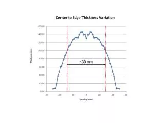
- Dimension 30 (mm) won’t be made exactly as 30 (mm) - It may be made as 30.10 (mm) or 30.05 (mm). - maximum may be 30.10 (mm) Fig. 1 (a) 30 (b) 30 TOLERANCES - IntroductionNearly impossible to make the part to the exact dimension by any means of manufacturing approach - tolerances of the dimension. handout 10a
Introduction - situations for assembly of (a) and (b)? (a) 30.01 (shaft) (b) 30.005 (hole) (a) and (b) are impossible to be assembled without any special treatment (a) 30.00 (shaft) (b) 30.20 (hole) (a) and (b) are assembled with a possibility of poor Function of the system (see Figure 2) handout 10a
L’ Introduction Figure 2 . L handout 10a
Introduction In summary, designers need to specify tolerances for (a) Parts manufacturing interchangeable (b) System function satisfactorily with low cost Since greater accuracy costs more money, the designer will not specify the closest tolerance, but instead will specify as generous a tolerance as possible. handout 10a
Introduction Objectives of the lecture: • To learn principles behind those rules or standards for determining tolerances. • To learn procedure of using the standards for determining tolerances. handout 10a
Basic Concept Definition of Tolerance: Tolerance is the total amount a specific dimension is permitted to vary, which is the difference between the maximum and the minimum limits. Tolerance is always a positive number handout 10a
Basic Concept Three types of fits (a) 1.247 - 1.248 shaft (b) 1.250-1.251 hole Clearance fit (a) 1.2513-1.2519 shaft (b) 1.2500-1.2506 hole Interference fit (a) 1.2503-1.2509 shaft (b) 1.2500-1.2506 hole Transition fit handout 10a
upper-limit and lower-limit Lower limit Upper limit Shaft tolerance = 1.248-1.247=0.001 Hole tolerance = 1.251-1.250=0.001 Limits: The maximum and the minimum sizes indicated by a tolerance dimension. The limits for hole are 1.250” and 1.251” The limits for shaft are 1.248” and 1.247” The tolerance can also be defined as upper limit – lower limit on one same dimension handout 10a
Allowances: an intentional difference between the maximum material limits of mating parts. It is the minimum clearance (positive allowance) or maximum interference (Negative allowance) between parts.
Hole limit Shaft limit Allowances: Allowance = Min Hole – Max Shaft • For the previous example, • Clearance fit • Allowance = 1.250-1.248=0.002 Allowance is associated with two dimensions of two parts that form a fit handout 10a
Basic concept ExamplesFigure 5 Shaft tolerance = 1.248 - 1.247 =0.001 Hole tolerance= 1.251-1.250= 0.001 Allowance=1.250-1.248= 0.02 Max clearances=1.251-1.247= 0.04 handout 10a
The unilateral form The bilateral form The limit form 2.245 - 2.250 0.495 - 0.500 2.247-2.253 Tolerance representation handout 10a
In general or Positive First Large Limit on Top Small limit first Tolerance representation handout 10a
Standard • Standard (ISO, etc.): limits a freedom of choices but promotes the exchange of parts manufactured with • different approaches • different equipment • different worker • in different cultural and societal situations handout 10a
Standard Different countries and regions together to develop - Concepts - Rules - Systems handout 10a
Methodology for Determining Basic Size Basic Hole System Purpose: take a hole as a reference to determine the shaft limit given allowance and tolerances. the minimal hole size as the basic size. Reason: in some applications, the hole can be made more precise (Reamers, Broachers, Gages), while the machining of the shaft varies. handout 10a
Methodology for Determining Basic Size Basic Shaft System Reason: in some applications, the shaft could be better made as a reference Different fits with the same shaft handout 10a
Methodology for Determining Basic Size Basic Shaft System the maximal shaft size as the basic size Reason: Cold-finished shaft. - cold forging - cold molding - cold rolling handout 10a
Basic hole system Basic shaft system Methodology for Determining Basic Size Basic size =0.5 Example 0.502 0.498 0.500 0.495 0.500 0.499 0.505 0.502 handout 10a
Example: Basic Hole System Given: Tolerance for the hole = 0.002 Tolerance for the shaft = 0.03 Allowance = 0.02 Basic dimension =0.500 To determine: (a) the limit of the shaft (b) the limit of the hole Solution: handout 10a
Known: - Allowance=0.02 - Tolerance for hole=0.002 - Tolerance for shaft=0.03 - Because Basic hole system, Basic dimension=0.5, Min. Hole dimension = 0.5 • Therefore: • Max. Hole dimension = Min. Hole + Hole tolerance • = 0.5 + 0.002 = 0.502 • - Max. Shaft dimension = Min. Hole – Allowance • = 0.5 - 0.02 = 0.498 • - Min. Shaft dimension = Max. Shaft + Shaft tolerance = 0.498 - 0.03 = 0.495 handout 10a
0.502 0.498 0.500 0.495 Basic hole system The basic size = 0.500 Example handout 10a
Basic shaft system 0.500 0.499 Known: Allowance=0.002 Tolerance for hole= 0.003 Tolerance for shaft= 0.001 The minimal hole size: 0.500+0.002=0.502 Example Basic shaft system 0.505 0.502 The maximal hole: 0.502+0.003=0.505 The minimal shaft size: 0.500-0.001=0.499 The basic size=0.500 handout 10a