Datapath and Control
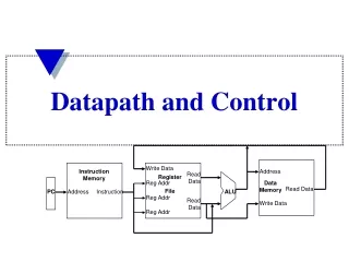
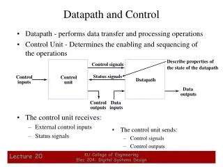
Datapath - performs data transfer and processing operations Control Unit - Determines the enabling and sequencing of the operations The control unit receives: External control inputs Status signals. The control unit sends: Control signals Control outputs.

Datapath and Control
E N D
Presentation Transcript
Datapath - performs data transfer and processing operations Control Unit - Determines the enabling and sequencing of the operations The control unit receives: External control inputs Status signals The control unit sends: Control signals Control outputs Describe properties ofthe state of the datapath Control signals Status signals Control Control Datapath inputs unit Data outputs Control Data outputs inputs Datapath and Control KU College of Engineering Elec 204: Digital Systems Design
Control Unit Types • Two distinct classes: • Programmable • Non-programmable. • A programmable control unit has: • A program counter (PC) or other sequencing register with contents that points to the next instruction to be executed • An external ROM or RAM array for storing instructions and control information • Decision logic for determining the sequence of operations and logic to interpret the instructions • A non-programmable control units does not fetch instructions from a memory and is not responsible for sequencing instructions • This type of control unit is our focus in this chapter KU College of Engineering Elec 204: Digital Systems Design
Algorithmic State Machines • The function of a state machine (or sequential circuit) can be represented by a state table or a state diagram. • A flowchart is a way of showing actions and control flow in an algorithm. • An Algorithmic State Machine (ASM) is simply a flowchart-like way to specify state diagrams for sequential logic and, optionally, actions performed in a datapath. • While flowcharts typically do not specify “time”, an ASM explicitly specifies a sequence of actions and their timing relationships. KU College of Engineering Elec 204: Digital Systems Design
State Box (a rectangle) Scalar Decision Box (a diamond) Vector Decision Box (a hexagon) Conditional Output Box (oval). The State Box is a rectangle, marked with the symbolic state name, containing register transfers and output signals activated when the control unit is in the state. The Scalar Decision Box is a diamond that describes the effects of a specific input condition on the control. It has one input path and two exit paths, one for TRUE (1) and one for FALSE (0). The Vector Decision Box is a hexagon that describes the effects of a specific n-bit (n > 2) vector of input conditions on the control. It has one input path and up to 2n exit paths, each corresponding to a binary vector value. The Conditional Output Box is an oval with entry from a decision block and outputs activated for the decision conditions being satisfied. ASM Primitives KU College of Engineering Elec 204: Digital Systems Design
State Box (Optional state code) (Symbolic Name) • A rectangle with: • The symbolic name for the state marked outside the upper left top • Containing register transfer operations and outputs activated within or while leaving the state • An optional state code, if assigned, outside the upper right top IDLE 0000 (Register transfers or outputs) R ← 0 RUN KU College of Engineering Elec 204: Digital Systems Design
Scalar Decision Box (True Condition) • A diamond with: • One input path (entry point). • One input condition, placed in the center of the box, that is tested. • A TRUE exit path taken if the condition is true (logic 1). • A FALSE exit path taken if the condition is false (logic 0). (False Condition) (Input) 0 1 START KU College of Engineering Elec 204: Digital Systems Design
(Binary Vector Values) (Binary Vector Values) (Vector of InputConditions) 00 10 01 Z, Q0 Vector Decision Box • A hexagon with: • One Input Path (entry point). • A vector of inputconditions, placed in thecenter of the box, that istested. • Up to 2n output paths. The path taken has a binary vector value that matches the vector input condition KU College of Engineering Elec 204: Digital Systems Design
Conditional Output Box From Decision Box(es) • An oval with: • One input path from a decision box or decision boxes. • One output path • Register transfers or outputs that occur only if the conditional path to the box is taken. • Transfers and outputs in a state box are Moore type - dependent only on state • Transfers and outputs in a conditional output box are Mealy type - dependent on both state and inputs (Register transfers or outputs) R← 0 RUN KU College of Engineering Elec 204: Digital Systems Design
IDLE R← 0 AVAIL 0 1 START PC ← 0 INIT Connecting Boxes Together • By connecting boxes together, we begin to see the power of expression. • What are the: • Inputs? • Outputs? • Conditional Outputs? • Transfers? • Conditional Transfers? KU College of Engineering Elec 204: Digital Systems Design
Entry IDLE ASM BLOCK AVAIL START R← R + 1 R ← 0 Exit 0 1 Q0 Exit Exit MUL1 MUL0 ASM Blocks • One state box alongwith all decision andconditional outputboxes connectedto it is called an ASMBlock. • The ASM Blockincludes all items on thepath from the currentstate to the same or otherstates. KU College of Engineering Elec 204: Digital Systems Design
Clock cycle 1 Clock cycle 2 Clock cycle 3 Clock START Q 1 Q 0 MUL 1 IDLE State AVAIL 0034 0000 A ASM Timing • Outputs appear while in the state • Register transfers occur at the clock while exiting the state - New value occur in the next state! KU College of Engineering Elec 204: Digital Systems Design
ASM Design Example • Input: Start signal – S Output: 2 flip-flops – E and F One 4-bit binary counter – A (A3 A2 A1 A0) • A start signal S starts the system by clearing the counter A and the F flip-flop. With the next clock pulse the counter incremented. The counter continues to be incremented until the operations stop. The counter bits A3 and A2 are used to control the sequence: • If A2 = 0 E is cleared • If A2 = 1 E is set • If A3 = 0 the count continues • If A3 = 1 F is set on the next clock pulse, and system stops counting. KU College of Engineering Elec 204: Digital Systems Design