Download

1 / 23
230 likes | 241 Views
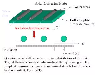
This workshop discusses examples of failures in collector cooling design, focusing on issues related to water quality and temperature rise. It explores minimum flow rates, turbulent flow in cooling channels, stress on the collector from hydrostatic pressure, and more.

E N D
Collector Cooling Design example Failures in the field Water quality ILC Power and Cooling VM Workshop
Temperature Rise of water and minimum flow rates • Minimum flow rate is determined • By: • Inlet water temperature • DC operation at full duty • Desired DT of water • Collector Surface Temperatures below 90C (10C margin?) • Turbulent Flow in cooling channels • (Without RF 125 kW • With RF 47 kW) ILC Power and Cooling VM Workshop
Simplified Klystron Collector Geometry Example • F, (gpm) • L, length of duct (in) • n, number of ducts • A, cross sectional area of duct • f, duct geometry factor (4pA/p2) p, perimeter of duct L-band Spec 1.4 typ “Cooling of Electronic Equipment”, Al Scott, 1974, John Wiley & Sons, ILC Power and Cooling VM Workshop
Laminar to Turbulent Flow (water) Laminar • F, (gpm) • n, number of ducts • A, cross sectional area of duct • f, duct geometry factor (4pA/p2) • p, perimeter of duct In the example F>5 gpm for turbulent flow “Cooling of Electronic Equipment”, Al Scott, 1974, John Wiley & Sons, ILC Power and Cooling VM Workshop
Temperature Rise of Duct above Water for Turbulent Flow ILC Power and Cooling VM Workshop
Summary of Example • DC power into the collector, 125 kW • 22 gpm input at 35C • Pressure drop .1bar • Water DT, 18C • Copper surface DT, 15C above water • Collector Cooling surface temperature, 35+18+21=74C ILC Power and Cooling VM Workshop
Stresses in Collector from Hydrostatic pressure • Margin needed to prevent copper plastic deformation • Assume full force on the inner collector bucket (i.e. no mechanical support from outer bucket) Factor of 2 safety at 6.5 bar max ***Max Pressure in ILC Spec is 10 bar (160 psi) *** This could be a problem. ILC Power and Cooling VM Workshop
A Collection of Collector cooling/design failures • PEP-II • LHC • APT • KEKB ILC Power and Cooling VM Workshop
Vacuum leak identified at the collector braze joint on each of the 3 failed Marconi klystrons. When trying to find the, found each of the collector bodies had deformed. Deformation occurred in approximately the same location for all 3 klystrons. Excessive heating of the collector the primary cause. Marconi S/N 02 and 03 rebuilt at CPI with an improved collector design: has longitudinal cooling channels as opposed to radial channels. Baffled water circulation to specifically direct water around the collector braze joint. Marconi Klystron (Oct 2002)PM-RF-System-Status-MAC-10-09-03.ppt Peter McIntosh ILC Power and Cooling VM Workshop
lhc.web.cern.ch/lhc/icc/icc2007-03/brunner.pdf ILC Power and Cooling VM Workshop
Rees, D. Los Alamos Nat. Lab., NM; Vacuum Electronics Conference, 2000. Mixed phase collector cooling system allowing for boiling and recondensation Fringing magnetic field into the collector was inconsistent from tube to tube. Collector overheating and the mechanical support system allowed the collectors to droop Improved inner bucket support system and changed operating conditions to minimize full dc beam power into the collector ILC Power and Cooling VM Workshop
KEKB APAC98 Vapor Cooled Collectors ILC Power and Cooling VM Workshop
Cooling Water specifications • Scale formation tests • CPI specifications • Thales specs ILC Power and Cooling VM Workshop
Scale formation occurs over time. High flow rates and low power densities slow the rate of formation Ion and Oxygen removal is optimum ILC Power and Cooling VM Workshop
Thales ILC Power and Cooling VM Workshop
Tube Specs • TH2104C (5 MW tube) • ILC 10 MW tube ILC Power and Cooling VM Workshop
5 MW tube 240/3.8=63 gpm ILC Power and Cooling VM Workshop
10 MW ILC Spec This may be a problem due to hydrostatic stresses in the collector 22 gpm ILC Power and Cooling VM Workshop
Appendix • Pressure Drop for Turbulent Flow • Evaporative Cooling requirements ILC Power and Cooling VM Workshop
Pressure Drop for Turbulent Flow in 3/8 in diameter duct • F, (gpm) • L, length of duct (in) • n, number of ducts • A, cross sectional area of duct • f, duct geometry factor (4pA/p2) p, perimeter of duct ILC Power and Cooling VM Workshop
Limits of Evaporative Cooling ILC Power and Cooling VM Workshop