Download
1 / 16
170 likes | 376 Views
AMCOM MK66 Guidance Module. 04-05-2005. IMU. Converting acceleration information to position data Performing double integration Using rectangular integration method Ready for testing and integration into simulation software. Software optimization. Subroutine optimization

E N D
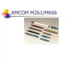
AMCOM MK66 Guidance Module 04-05-2005
IMU • Converting acceleration information to position data • Performing double integration • Using rectangular integration method • Ready for testing and integration into simulation software
Software optimization • Subroutine optimization • Computational requirement reduction • In-memory space reduction • Completion of roll compensation
Software: What’s left • Completion of serial I/O routines • Integration of IMU code module • Serial-based testing
Canard/Canard Cam Design • One-piece construction • Built-in mechanical stop • NACA airfoil to be CNCed • Fillet right angles to reduce stress concentrations
Canard Actuation Mechanism • Machined as four basic components • Positive stop built into upper box half • Locks canard at 90 degrees • Size: .75” x .4”
Frame • Machined from single piece of material (13/16” thick) • Canard Mechanism mount oriented at 45 degree angle • .707” thick at maximum • .25” thick frame bulk • Symmetrical • Fillets to reduce stress concentrations
Gear Selection • Miter gear pair (non-backdriving) • 1” pitch diameter on larger gear (mounted to canard mechanism) • .5” pitch diameter on smaller gear (mounted to servomotor)
To Do • Finish designing gear mount • Order helical torsion spring, frame material, canard actuation material • Meet with AMCOM • Machine