Download
1 / 1
30 likes | 217 Views
Cavitation in Sonolators. David Ryan 1 2 , Mark Simmons 1 , Mike Baker 2 – June 2012. 1 University of Birmingham, UK; 2 Unilever Research and Development, Port Sunlight, UK. Acoustic results and frequency spectra. Aims and Objectives.

E N D
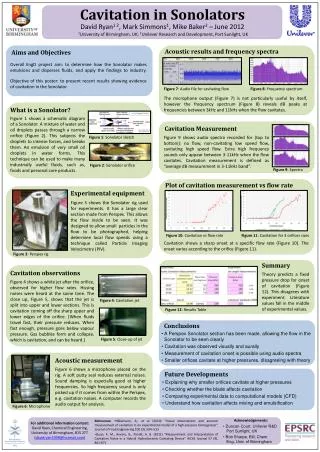
Cavitation in Sonolators David Ryan1 2,Mark Simmons1,Mike Baker2 – June 2012 1University of Birmingham, UK; 2Unilever Research and Development, Port Sunlight, UK Acoustic results and frequency spectra Aims and Objectives Overall EngD project aim: to determine how the Sonolator makes emulsions and disperses fluids, and apply the findings to industry. Objective of this poster: to present recent results showing evidence of cavitation in the Sonolator. Figure 7: Audio file for cavitating flow Figure 8: Frequency spectrum The microphone output (Figure 7) is not particularly useful by itself, however the frequency spectrum (Figure 8) reveals dB peaks at frequencies between 3kHz and 11kHz when the flow cavitates. What is a Sonolator? Figure 1 shows a schematic diagram of a Sonolator. A mixture of water and oil droplets passes through a narrow orifice (Figure 2). This subjects the droplets to intense forces, and breaks them. An emulsion of very small oil droplets in water forms. This technique can be used to make many industrially useful fluids, such as, foods and personal care products. Cavitation Measurement Figure 9 shows audio spectra recorded for (top to bottom): no flow, non-cavitating low speed flow, cavitating high speed flow. Extra high frequency sounds only appear between 3-11kHz when the flow cavitates. Cavitation measurement is defined as “average dB measurement in 3-11kHz band”. Figure 1: Sonolator sketch Figure 2: Sonolator orifice Figure 9: Spectra Plot of cavitation measurement vs flow rate Experimental equipment Figure 3 shows the Sonolator rig used for experiments. It has a large clear section made from Perspex. This allows the flow inside to be seen. It was designed to allow small particles in the flow to be photographed, helping determine local flow speeds using a technique called Particle Imaging Velocimetry (PIV). Figure 10: Cavitation vs flow rate Figure 11: Cavitation for 3 orifices sizes Cavitation shows a sharp onset at a specific flow rate (Figure 10). The onset varies according to the orifice (Figure 11). Figure 3: Perspex rig Summary Cavitation observations Theory predicts a fixed pressure drop for onset of cavitation (Figure 12). This disagrees with experiment. Literature values fall in the middle of experimental values. Figure 4 shows a white jet after the orifice, observed for higher flow rates. Hissing noises were heard at the same time. The close up, Figure 5, shows that the jet is split into upper and lower sections. This is cavitation coming off the sharp upper and lower edges of the orifice. (When fluids travel fast, their pressure reduces. When fast enough, pressure goes below vapour pressure. Gas bubbles form and collapse, which is cavitation, and can be heard.) Figure 4: Cavitation jet Figure 12: Results Table Conclusions • A Perspex Sonolator section has been made, allowing the flow in the Sonolator to be seen clearly • Cavitation was observed visually and aurally • Measurement of cavitation onset is possible using audio spectra • Smaller orifices cavitate at higher pressures, disagreeing with theory Figure 5: Close-up of jet Acoustic measurement Figure 6 shows a microphone placed on the rig. A soft putty seal reduces external noises. Sound damping is especially good at higher frequencies. So high frequency sound is only picked up if it comes from within the Perspex, e.g. cavitation noises. A computer records the audio output for analysis. Future Developments • Explaining why smaller orifices cavitate at higher pressures • Checking whether the blade affects cavitation • Comparing experimental data to computational models (CFD) • Understand how cavitation affects mixing and emulsification Figure 6: Microphone • Acknowledgements: • Duncan Court, Unilever R&D Port Sunlight, UK • Bob Sharpe, Bill; Chem Eng, Univ. of Birmingham • References: •Håkansson, A., et al (2010) “Visual observations and acoustic measurement of cavitation in an experimental model of a high-pressure homogenizer” Journal of Food Engineering 100 (3), 504–513 • Quan, K. M., Avvaru, B., Pandit, A. B. (2011) "Measurement and Interpretation of Cavitation Noise in a Hybrid Hydrodynamic Cavitating Device" AIChE Journal 57 (4), 861-871 For additional information contact: David Ryan, Chemical Engineering, University of Birmingham, B15 2TT (davidryan1998@hotmail.com)