
Source Terms
E N D
Presentation Transcript
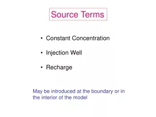
Source Terms • Constant Concentration • Injection Well • Recharge May be introduced at the boundary or in the interior of the model
Q Constant Concentration (Z&B, p. 283) cs e.g., NAPL source area at boundary
Injection Well Qcs well
Recharge R, cs Mass Flux = R (x y)cs
Problem Set #3 Source Terms and Chemical Reactions • Constant Concentration • Injection Well • Recharge • retardation • 1st order decay
Confined layers Problem Set #3 Two Layers This screen shows a constant concentration source. Contours of head are also shown.
Note the water table Flow field for an unconfined upper layer with areal recharge and a recharge source cell.
Problem Set #3 Parts 1 and 2: Produce breakthrough curves under different assumptions about the source term and chemical reactions.
Numerical error caused by high Peclet number Problem Set #3 – Part 3 - Remediation TVD Solution
Central Finite Difference Solution 100 m grid spacing
Numerical error caused by high Peclet number Problem Set #3 – Part 3 - Remediation TVD Solution
Cr < 1 Courant Number Pe < 4 Peclet Number
50 m grid Pumping well is represented by 4 nodes
TVD solution 50 m grid spacing upper left node in the pumping complex Peclet number = 2.5 100 m grid spacing Peclet number = 5
TVD Solution 50 m grid – near center of pumping complex 100 m grid
TVD Solution 50 m grid – upper left node of pumping complex 55 50 100 m grid Central difference 50 m grid – near center of pumping complex 60 100 m grid 50