Download
1 / 32
320 likes | 348 Views
Development of a next-generation microwave SQUID multiplexer for high-performance metallic magnetic calorimeters, achieving signal rise times <100ns and superior temperature signal decay. The design incorporates advanced software-defined radio techniques, achieving high channel density and reduced noise levels. Fine-tuning of resonance frequencies and precise channel identification ensures optimal performance.

E N D
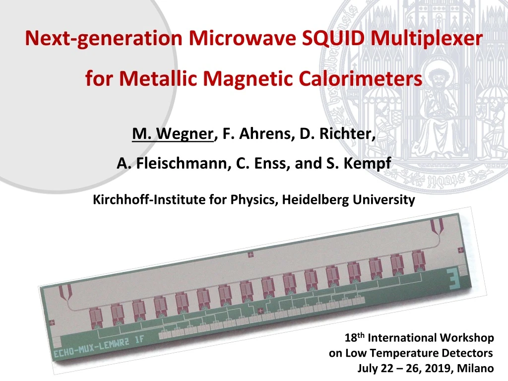
Next-generation Microwave SQUID Multiplexer for Metallic Magnetic Calorimeters M. Wegner, F. Ahrens, D. Richter, A. Fleischmann, C. Enss, and S. Kempf Kirchhoff-Institute for Physics, Heidelberg University 18th International Workshop on Low Temperature Detectors July 22 – 26, 2019, Milano
Next-generation Microwave SQUID Multiplexer for Metallic Magnetic Calorimeters M. Wegner, F. Ahrens, D. Richter, A. Fleischmann, C. Enss, and S. Kempf Kirchhoff Institute for Physics, Heidelberg University Poster Nick Karcher Session B: Thursday – 17:45 This Contribution First multiplexed MMC readout 18th International Workshop on Low Temperature Detectors July 22 – 26, 2019, Milano Multiplexer Development Software Defined Radio
Metallic MagneticCalorimeters Signal rise t0<100ns Temperature Signal decay t1>1ms DT~ 1mK Time [1] A. Fleischmann et al., AIP Conf. Proc.1185 (2009), 571 [2] S. Kempf et al., J. Low Temp. Phys.193 (2018), 365 1
Microwave SQUID Multiplexing 2 coaxes + 1 HEMT = about 1000 MMC pixels [3] K. Irwin and K. Lehnert, Appl. Phys. Lett. 85 (2004), 2107-9 [4] J. A. B. Mates et al., Appl. Phys. Lett. 92 (2008), 023514 2
Heidelberg MUX Design 2017 15 mm Transmission lineresonators rf-SQUIDs Design NIST - inspired • Readout viasuperconductingfluxtransformer • Impedancematchingof SQUID/Detector • Strong limitations on filtering • Strong couplingbetweeninput/mod. coil • Small frspacingrequiresvery high fabaccuracy 70µm Mod. coil Input coil [5] J. A. B. Mates, PhD Thesis (2011)[7] M. Wegner et al., J. Low Temp. Phys.193 (2018), 462 [6] J. A. B. Mates et al., Appl. Phys. Lett. 92 (2008), 023514 [8] S. Kempf et al., AIP Adv.7 (2017), 015007 3
Heidelberg LEMUX Design 2019 15 mm Transmission lineresonatorLumpedelementresonator Higher channeldensity Post-processing possible Reduced TLS noiselevel [9] S. Doyle et al., J. Low Temp. Phys.151 (2008), 530 [10] O. Noroozianet al., AIP Conf. Proc. 1185 (2009), 148 4
Heidelberg LEMUX Design 2019 15 mm Feedline CC Couplingcapacitor Lumpedelement resonator LRes CRes 400µm LT Load inductor Ic LS Non-hysteretic rf-SQUID Lin Input coil 4
Heidelberg LEMUX Design 2019 15 mm Parallel gradiometerwith 4 washers 240µm 4
Heidelberg LEMUX Design 2019 15 mm Parallel gradiometerwith 4 washers LT Lmod 240µm Lin Input coil Modulation coil Resonator 4
Measured Multiplexer Characteristics Fluxdependenceof transmissionamplitude Fluxdependenceof resonancefrequency bL = 0.40, Dfmax = 730 kHz T = 4.2 K T = 4.2 K BW = 2.7 MHz • Very goodagreementbetweenmeasureddata and multiplexer model • Extracted multiplexer parameterscloseto design values 5
Fine-Tuning ofResonanceFrequencies Before post-processing After post-processing Bare resonators Bare resonators T = 4.2 K T = 4.2 K • Fine-tuning ofresonancefrequenciesallowsforspacingDfr = 10MHz • Channel identificationrequiredifresonancefrequenciesswapposition 6
Fine-Tuning ofResonanceFrequencies Before post-processing After post-processing Recalculate optimal resonatorparameters Adjustparameters withetchingprocess Determineresonance frequencypattern T = 4.2 K T = 4.2 K [11] X. Liu et al., Appl. Phys. Lett.111(25) (2017), 252601 • Fine-tuning ofresonancefrequenciesallowsforspacingDfr = 10MHz • Channel identificationrequiredifresonancefrequenciesswapposition 6
Fine-Tuning ofResonanceFrequencies Before post-processing After post-processing T = 4.2 K T = 4.2 K • Fine-tuning ofresonancefrequenciesallowsforspacingDfr = 10MHz • Channel identificationrequiredifresonancefrequenciesswapposition 6
Multiplexer Channel Identification No parallel inductance: Strong couplingMmod,1 Midsize parallel inductance: Medium couplingMmod,2 Small parallel inductance: WeakcouplingMmod,3 Parallel inductance Common mod. coil Mmod,1 = 66 mA/F0 Mmod,2 = 82 mA/F0 Mmod,3 = 101 mA/F0 des des des 7
Multiplexer Channel Identification Mmod,2 = 87 mA/F0 Mmod,1 = 66 mA/F0 Mmod,3 = 106 mA/F0 Parallel inductance Common mod. coil Mmod,1 = 66 mA/F0 Mmod,2 = 82 mA/F0 Mmod,3 = 101 mA/F0 des des des • Parallel inductancesareremovedduringfine-tuning processofresonators 7
Multiplexer Power Dependence For MMC readout: White flux noisecurrentlyHEMT limited Low Prf Stronglyasymmetric resonancecurves Decreasingresonance frequency shift 8
Multiplexer Power Dependence Shift to high fr Shift to lowfr Nofr shift Very lowreadoutpowers: IS(t) containsonlyf [12] P. Hansma, J. Appl. Phys. 44 (1973), 4919 [13] R. Rifkin et al., J. Appl. Phys.47 (1976), 2645 9
Multiplexer Power Dependence Higher harmonicsfor higherreadoutpowers Higher readoutpowers: IS(t) containsf, 2f, 3f, … filteredbyresonator [12] P. Hansma, J. Appl. Phys. 44 (1973), 4919 [13] R. Rifkin et al., J. Appl. Phys.47 (1976), 2645 9
Multiplexer channelidentification Taylor expansiontofirstorder in bL: Bessel functionsof first kind Screening currentsrespected withbl in 2nd order Optimal readout power bLrespected to 2nd order Low Prf 10
Multiplexer channelidentification Taylor expansiontofirstorder in bL: Bessel functionsof first kind Screening currentsrespected withbl in 2nd order MUX Model explainsasymmetriccurves Low Prf 10
Outlook: LEMUX withrf-SQUID Arrays • Array with N = 16 identicalrf-SQUIDs: • Resonator coupling MTfactor 4 smaller • Readout power Prf factor 16 higher • HEMT fluxnoisecontributionsmaller CC Resonator CRes LRes Input coil LT Nidentical SQUID cells Mod. coil Single SQUID cell 35 µm 11
Outlook: LEMUX withrf-SQUID Arrays Fluxdependenceofresonance frequency at lowreadoutpowers Power dependenceof maximum resonancefrequency shift Expected optimal readout power N = 16 • Weaklycoupledrf-SQUID arraybehavesas a medium coupledsinglerf-SQUID • Optimal readout power: olddevice -75 ... -70 dBm • newdevice -60 … -55 dBm 10 … 15 dB higherPrf 12
Summary & Outlook Next step: Scalingupto 400 channelswith 10 MHz spacing 13
Summary & Outlook Next step: Scalingupto 400 channelswith 10 MHz spacing 13
Power dependent multiplexer model • Approximation forbL ≈ 0
Power dependent multiplexer model • Approximation forsmallbL
Power dependent multiplexer model 1 No current in resonator: IT = 0 Frf = 0 No shift of fr Small current in resonator: 0 < IT < Imax 0 < Frf < Fmax Small shift of fr Maximum current in resonator: IT = Imax Frf < Fmax Maximum shift of fr 1 2 2 3 3 Fdc = 0
Quality factorsof bare resonators Bare resonatorarray • 16 resonatorswithspacing 10 MHz • Qi ~ 100.000 and BW ~ 1 MHz
Post-processingoflumpedelementresonators • Redregionbefore post-processing: 0.12% * 4 GHz ~ 4.8 MHz • Redregion after post-processing: 0.025% * 4 GHz ~ 1 MHz
Resonator IDC and couplersimulations Resonator inductanceLfixedto 2 nH 25 CouplerCCfor 25 Chips simulated for 4 … 8 GHz for BW = 1 MHz Cressimulatedfor Chip 1 of 25


