Polarized Electron Beam at CEBAF
260 likes | 497 Views
Polarized Electron Beam at CEBAF. Matt Poelker 13 June, 2006. Polarized Source Group: M. Poelker, P. Adderley, J. Brittian, J. Clark, J. Grames, J. Hansknecht, James McCarter, M. Stutzman, K. Surles-Law. (3 scientists, 4 technical staff, 2 graduate students). Science and Technology Review

Polarized Electron Beam at CEBAF
E N D
Presentation Transcript
Polarized Electron Beam at CEBAF Matt Poelker 13 June, 2006 Polarized Source Group: M. Poelker, P. Adderley, J. Brittian, J. Clark, J. Grames, J. Hansknecht, James McCarter, M. Stutzman, K. Surles-Law (3 scientists, 4 technical staff, 2 graduate students) Science and Technology Review Jefferson Lab June 12-13, 2006
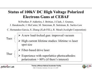
Highlights Since the Last S&T Review • Beam Polarization 85% typical, 80% guaranteed • New Fiber-Based Drive Laser: high power, reliable • Parity Violation Experiments: becoming more routine • Load-Locked Gun developments for high current future experiments • Low Voltage Mott polarimeter for photocathode studies
0.6 GeV linac (20 cryomodules) 1497 MHz 67 MeV injector RF-pulsed drive lasers (2 1/4 cryomodules) 1497 MHz RF separators 499 MHz A B C B 499 MHz, Df = 120 A C B A C Pockels cell Chopper Wien filter Double sided septum Gun Continuous Electron Beam Accelerator Facility
Everyone Gets Beam from Pol. Electron Gun! • CEBAF’s first polarized e-beam experiment 1997 • Now polarized beam experiments comprise ~ 80% of our physics program • All beam originates from the same 0.5mm spot on one photocathode inside 100kV GaAs photogun (the thermionic gun was removed in 2000) • For example, during April 2006 there were three high profile polarized beam experiments on the floor simultaneously; • Hall A: Gen (10uA) • Hall B: GDH (3nA) • Hall C: G0 Backward Angle (60uA)
Strained GaAs: GaAs on GaAsP Superlattice GaAs: Layers of GaAs on GaAsP Bulk GaAs 100 nm 100 nm 14 pairs “conventional” material QE ~ 0.15% Pol ~ 75% @ 850 nm No strain relaxation QE ~ 0.8% Pol ~ 85% @ 780 nm High QE ~ 10% Pol ~ 35% Both are results of successful SBIR Programs Photocathode Material
2 2 P I P I sup. = 1.38 str. Beam Polarization at CEBAF Experiment Figure of Merit Reasonable to request >80% polarization in PAC proposals
No depolarization over time! Polarization Oct 13 QE dropped by factor of 2 Nov 9 Anodized edge: a critical step Superlattice Photocathodes • Success required ~ 1 year of effort • Cannot be hydrogen cleaned (M. Baylac) • Arsenic capped (worked with vendor SVT) • No solvents during preparation! (M. Stutzman) M. Baylac et al., “Effects of atomic hydrogen and deuterium exposure on high polarization GaAs photocathodes” PRST-AB 8, 123501 (2005)
Chopper viewer DC drive laser, Most beam thrown away Efficient beam extraction prolongs operating lifetime of photogun Three independent RF-Pulsed lasers Lasers with GHz pulse repetition rates have been hard to come by B C A Synchronous Photoinjection Only electrons within 110 ps window can be accelerated. Electrons outside window are dumped in the chopper.
Commercial Ti-Sapphire Laser • 1st commercial laser w/ 499 MHz rep rate • Higher power compared to diode lasers • Wavelength tunable for highest polarization • Feedback electronics to lock optical pulse train to accelerator RF
System Availability FY05Q4 – FY06Q3 Realign Ti-Sapphire lasers
New Fiber-Based Drive Laser Ti-Sap power J. Hansknecht and M. Poelker, Phys. Rev. ST Accel. Beams 9, 063501 (2006) • CEBAF’s last laser! • Gain-switching better than modelocking; no phase lock problems • Very high power • Telecom industry spurs growth, ensures availability • Useful because of superlattice photocathode (requires 780nm)
Normal Ops; Three beams at 499 MHz Beat Frequency Technique; One laser at 467.8125 MHz B C A Other Benefits of Fiber Drive Laser • Maybe replace some lossy optics components with telecom stuff? • Green version for RF-pulsed Compton Polarimetry, FEL Drive Laser • “Beat Frequency Technique” to create Low Rep Rate Beam for Particle Identification at Halls: Every 15th pulse delivered to hall: 31 MHz beam
1999 2008 What is “Parity Quality”? Helicity-correlated asymmetry specifications * Results affected by electronic crosstalk at injector. ** Results at Hall A affected by Hall C operation. Spec was met in 2005 run.
Routine Parity Violation Experiments? We need: • Long lifetime photogun (i.e., slow QE decay) • Stable injector (especially RF phases) • Properly aligned laser table, pockels cell (HAPPEx method) • Proper beam-envelope matching throughout machine for optimum adiabatic damping • Set the phase advance of the machine to minimize position asymmetry at target • Eliminate electronic ground loops: isolate electronics • Feedback loops; charge and position asymmetry • Specific requirements for each experiment; e.g., 31 MHz pulse repetition rate, 300 Hz helicity flipping, beam halo < , etc.,
What is HAPPEx Method? • Developed jointly with Source Group • Identify Pockels cells with desirable properties: • Minimal birefringence gradients • Minimal steering • Must be verified through testing! • Install Pockels cell using good diagnostics: • Center to minimize steering • Rotationally align to minimize unwanted birefringence • Adjust axes to get small (but not too small) analyzing power. • Adjust voltage to get maximum circular polarization! • Use feedback to reduce charge asymmetry. • Pockels cell voltage feedback maximizes circular polarization. • “Intensity Asymmetry” Pockels cell provides most rapid feedback. • During SLAC E158, both were used. • If necessary, use position feedback, keeping in mind you may just be pushing your problem to the next highest order. From G. Cates presentation, PAVI04 June 11, 2004
X position diff. (um) No HV HV + Y position diff. (um) HV - Translation (inches) Red, IHWP Out Blue, IHWP IN Origins of Helicity Correlated Beam Asymmetries Pockels Cell = active lens. Laser beam needs to pass through center of cell. From G. Cates presentation, PAVI04 June 11, 2004
New Developments High Current at High Polarization; Qweak to test standard model, 2008 180 uA at 85% polarization Higher Current, High Polarization; ~ > 1 mA Proposed new facilities ELIC, eRHIC High Current, No Polarization: ~ 100mA JLab FEL, electron cooling Solution: Fiber-based laser + Load locked gun
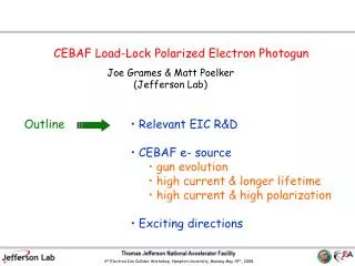
100 kV load locked gun Spot size diagnostic 1W green laser, DC, 532 nm Bulk GaAs Faraday Cup Baked to 450C Differential Pumps w/ NEG’s Insertable mirror NEG-coated large aperture beam pipe Focusing lens on x/y stage Load Locked Gun for Qweak Load locked gun: replace photocathodes quickly without bakeout. 8 hours versus 4 days.
Lifetime versus Laser Spot Size • Imperfect vacuum limits photocathode lifetime - damage from ion backbombardment • Can we increase operating lifetime by merely increasing the laser spot size? Same number electrons, same number ions, but distributed over larger area. • Exceptionally high charge lifetime, >1000C at beam current to 10mA! • Lifetime scales with laser spot size but simple scaling not valid. Factor 10 instead of factor 20. • Repeat measurements with high polarization photocathode material
New Load-Locked Gun • Better than first load locked gun design • No more edge-anodizing • Multiple samples • Better vacuum in high voltage chamber • No more venting • Less surface area • NEG coated • Longer photocathode lifetime? Commissioning now, Ready for installation Fall 2006
R&D program to obtain polarization > 90% Low voltage gun and mini-Mott polarimeter • “Spintronics”, with graduate student James McCarter and Dr. Stuart Wolf of University of Virginia. New photocathode material. • Collaborating with Dr. Tim Gay of University of Nebraska, polarimeter expert. (We have borrowed his polarimeter)
Conclusions and Future Plans The Polarized Source Group will: • Continue to deliver high polarization beam from long lifetime photoguns, using superlattice photocathodes and reliable fiber-based lasers • Install our new load-locked gun, to improve operating lifetime and support Qweak and other high current experiments • Support parity violation experiments that have tighter and tighter beam specifications • Continue working on exciting R&D projects: • Lifetime studies at current > 1 mA using load locked gun and high polarization photocathode material • Mini-Mott commissioning + photocathode studies to provide polarization >90%
Based on Optimistic 07 Budget We will: • Purchase more superlattice photocathode material, to keep us happy for many years, just in case vendor loses interest. • Purchase two more fiber-based laser systems (that would give us one for each hall plus green version for unpolarized beam experiments) • One more staff scientist to manage R&D program at Test Cave, to replace Maud Baylac who returned to France
Source Group Recent Publications Papers: “A High Average Current Polarized Electron Source with Long Cathode Operational Lifetime,” C. K. Sinclair, M. Poelker, P. A. Adderley, B. M. Dunham, J. C. Hansknecht, P. Hartmann, J. S. Price, P. M. Rutt, W. J. Schneider, and M. Steigerwald, in press. M. Poelker, J. Grames, J. Hansknecht, R. Kazimi, J. Musson, “Generation of Electron Microbunches at Low Repetition Rates Using Beat Frequency Technique”, in press. “Synchronous Photoinjection Using a Frequency-Doubled Gain-Switched Fiber-Coupled Seed Laser and ErYb-Doped Fiber Amplifier,” J. Hansknecht and M. Poelker, Phys. Rev. ST Accel. Beams 9, 063501 (2006) “The Effects of Atomic Hydrogen and Deuterium Exposure on High Polarization GaAs Photocathodes,” M. Baylac, P. Adderley, J. Brittian, J. Clark, T. Day, J. Grames, J. Hansknecht, M. Poelker, M. Stutzman, A.S. Terekhov and A.T. Wu, Phys. Rev. ST Accel. Beams 8, 123501 (2005). Conferences: “Probing Hadron Structure at CEBAF Using Polarized Electron Scattering,” M. Poelker, presented at the annual meeting of the American Physical Society, Dallas, TX, April 2006. “Operation of CEBAF photoguns at average beam current > 1 mA,” M. Poelker, J. Grames, P. Adderley, J. Brittian, J. Clark, J. Hansknecht, M. Stutzman, Polarized Sources and Targets Workshop, Nov. 14-17, 2005, Tokyo, JAPAN. “Polarized Photoguns and Prospects for Higher Current,” M. Poelker, Workshop on Energy Recovered Linacs, Jefferson Lab, March 19-22, 2005.
Photocathode QE Anisotropy, aka Analyzing Power Different QE for different orientation of linear polarization Origins of Helicity Correlated Beam Asymmetries minimum analyzing power maximum analyzing power GaAs photocathode Beam Charge Asymmetry Rotating Halfwaveplate Angle From G. Cates presentation, PAVI04 June 11, 2004
Origins of Helicity Correlated Beam Asymmetries Pockels cell aperture Gradient in phase shift leads to gradient in charge asymmetry which leads to beam profiles whose centroids shift position with helicity. Non-uniform polarization across laser beam + QE anisotropy… From G. Cates presentation, PAVI04 June 11, 2004