Download

1 / 11
110 likes | 135 Views
Learn about the features, installation, connections, and diagnostics of the AMC APS-PBC-60 power supply. Understand the output voltage and current for 12V and 24V operations, with battery charging details and protection mechanisms.

E N D
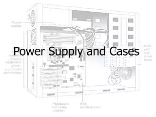
Topics for power supply AMC APS-PBC-60 • Overview and features • Connections • Installation • Diagnostic LED’s • Diagnostic relays • Output selection
AMC Power Supply – Overview and features • The AMC PBC-60 contains power supply and battery charger in one device • Output voltage • 12VDC operation 10-15V (7Ah or 14Ah) • 24VDC operation 20-30V (7Ah) • Output current • 12VDC operation 5A • 24VDC operation 2,5A • Output current for charging batteries • 12VDC operation 700mA • 24VDC operation 350mA • Periodical battery check every 6 minutes • Protection against deep discharge of battery • 9.5V for 12VDC operation • 19V for 24VDC operation
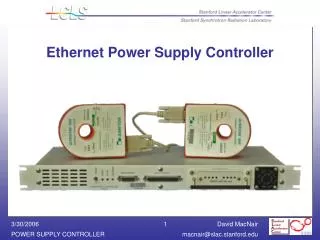
AMC Power Supply – Connections • AC 120V-240V • Battery 12V or 24V • Temperature Sensor* • AMC Power Supply Connector * Temperature compensation is realized by an external NTC-resistor
AMC Power Supply – Diagnostic LED‘s • When AC is ≥85V~ green LED AC is ON and relay AC is closed • When DC is ≥12V or ≥24V the green LED DC in ON and the relay DC is closed • When battery voltage is ≥11V (12V operation) or ≥22V (24V operation) the green LED BAT is ON and the relay BAT is closed For battery operation • When input voltage is <85V~ ≥24V the power supply changes to mode “Battery operation” and yellow LED BOP goes ON • The button POWER OFF is enable in battery operation mode only. Push it to switch off the output voltage A restart is only possible when AC mains voltage is already switched on 5 4 3 2 1
AMC Power Supply – Diagnostic relays • When AC mains is ≥85V~ green LED AC is ON and relay AC is closed • When DC is ≥12V or ≥24V the green LED DC in ON and the relay DC is closed • When battery voltage is ≥11V (12V operation) or ≥22V (24V operation) the green LED BAT is ON and the relay BAT is closed • Relay common 4 1 3 2
AMC Power Supply – Voltage output selection The power supply can operate in 12V- or 24V-mode. To change between the two modes, disconnect the input voltage and set the switch as shown in the figure.
AMC Power Supply – Setup summary 1. Select output voltage 2. Connect diagnostic UPS relay 5. Connect AC source 4. Connect battery 3. Connect to device
Connecting the Bosch power supply Warning: Never shortcut pin 1 and pin 6 respectively and pin 3 and pin 7 to share the power supply for internal electronics and peripherals like this was arranged with the AMC version 1! With AMC 2 this is now arranged with jumper settings.
AMC Grounding and shielding (Host interface) • The main grounding point at the AMC2 will be connected with pin 2 of the power supply connector. It is good practice to shield all wires carrying low level signals. • The AMC enables you to set up a central ground or shielding point, simply by setting a couple of jumpers. Set these jumpers only if ground or shield is not connected otherwise. • Setting jumper JP1 connects the AMC’s internal ground to the RS-485 host interfaceground. Jumper JP2 manages the signal ground (PAG). • Setting jumper JP1: • If the ground conductor and the shield are are not connected and • no partyline exists, JP1 is set as under A2 • a partyline exists, JP1 is set at the first device only as under A2 • Setting jumper JP2: • If the ground conductor and the shield are not connected and • no partyline exists, JP2 is set as under A3 • a partyline exists and PAG is connected, JP2 is set at the first device only as under A3 • a partyline exists and PAG is not connected, JP2 is set at all devices as under A3 • If the AMC is set to RS-232 mode, JP1 must be set as under A2.
AMC Grounding and shielding (extension interface) • Jumper B connects the AMC’s internal ground to the RS485 ground of the slave interface. • Jumper B shall only be set (B2) if the AMC powers all other peripheral devices which are directly connected to the AMC!