Download
1 / 45
510 likes | 713 Views
OPERATIONAL AMPLIFIERS LECTURE 17B. http://www.technologystudent.com/elec1/opamp1.htm. THE 741 OPERATIONAL AMPLIFIER. YOU TUBE: Operational Amplifier Tutorial & super microphone circuit. http://www.youtube.com/watch?v=TQB1VlLBgJE.

E N D
http://www.technologystudent.com/elec1/opamp1.htm THE 741 OPERATIONAL AMPLIFIER YOU TUBE: Operational Amplifier Tutorial & super microphone circuit http://www.youtube.com/watch?v=TQB1VlLBgJE
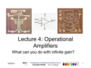
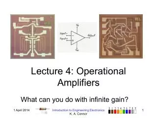
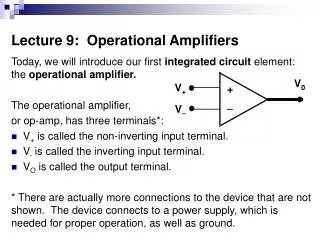
Operational Amplifiers (Op-Amp) were originally developed to build Analog Computers (and many Computer systems used in Aircraft still use them for this purpose). They are pre-built amplifier modules that are general enough to be plugged in almost anywhere an amplifier is needed. The advantage is that a small Op-Amp can often replace 20 or more discreet components. For people who like to build effects, mixers or other custom audio gear, they are a quick way to put together a highly functional amplifier stage. . There are many types of Op-Amps. The ones that we will discuss are the common voltage amplifier type, such as a '741', 'TL081' or 'TL082' that are packaged as 8 pin integrated circuits. You'll note that there are 2 inputs - an Inverting Input (marked with a - sign) and a Non-Inverting Input. There is a single output.
Most analog applications use an Op-Amp that has some amount of negative feedback. The Negative feedback is used to tell the Op-Amp how much to amplify a signal. In Figure 2, this Op-Amp will not amplify at all, it operates at Unity Gain, also known as a gain of 1. Unity Gain arrangements are also called Voltage Followers (See Figure 10) since they track the input voltage at the exact same level at output.
http://www.technologystudent.com/elec1/opyamp1.html THE OPERATIONAL AMPLIFIER USED AS AN AMPLIFIER WITH SENSORS
If you apply an input to either the - (Inverting) or the + (Non-Inverting) input, the Op-Amps output basically maintains the input level, but in the case of applying an input to the Inverting (-) input - Figure 3, the output signal will be 180 degrees out of phase with the input. In Figure 4, you see that the signal comes thru unchanged.
If an Op-Amp is an amplifier, how hard is it to get it to amplify the signal? Its very easy. The following 2 schematics show the 2 variations again, this time configured to amplify the signal.
If you wanted to make the gain adjustable, its only a matter of providing a way to alter the ratio of R2 to R1. Use a Potentiometer (variable resistor).
Vimeo.com: the op amp,start at 6:00 http://vimeo.com/1132525
Another common way that opamps are used are in comparator circuits. A comparator circuit will compare the voltage on the two inputs and then making the output high or low. This is accomplished by having one input the voltage reference (Vref) and the other input is the voltage input (Vin). Shown below are the two ways to hook up a comparator circuit. YOU TUBE: Comparator tutorial & clapper circuit http://www.youtube.com/watch?v=XLGqpCW8qrU
555 Timer Theory & Design The 555/556 timer is one of the most versatile and popular chips made. It is very inexpensive and easy to use. There are two basic modes of operation. 1: Monostable Mode and 2: Astable Mode. In the monostable mode the 555 acts as a "one - shot". It would be used for the purpose of obtaining a one pulse of variable length. In the astable mode the 555 will retrigger itself to output a stream of pulses of variable length. Basic information about the timers are shown below. http://www.technologystudent.com/elec_flsh/timer1a.html
Monostable Mode In the basic monostable mode the timer will be triggered by applying a negative pulse to pin 2. That will cause the output of the timer to output a pulse on pin 3 for a time period determined by the values of R1 and C1 in the circuit below. The supply voltage has no effect on the length of the pulse. The formula to determine the duration of the output pulse is as follows T = R1 x C1. For example if R1= 100k ohms and C1= 10uf then the length of the pulse would be 1 second. Vimeo.com: monostable 555 timer http://vimeo.com/1132421
Astable Mode In the astable mode of operation pin 2 and 6 are tied together to cause the timer to retrigger itself. The output pulse is on pin 3. The output pulse is shown in the diagram below. Vimeo.com: Astable - 555 Timer http://vimeo.com/1132468
Ignition Coil Driver This design uses a 555 timer and three 2n3055 switching transistors to provide a variable frequency, variable voltage input to an automotive ignition coil. Normal output is 25kV when run at 12v input and at the coil's resonant frequency (8kHz). Increasing the voltage output to about 50kV is possible if the input voltage is increased to 34v, however this risks burning out the switching transistors when the system is operated for an extended time.
Hexadecimal to Decimal Number Conversion In order to make conversion of a hexadecimal number to decimal, each hexadecimal digit should be multiplied with the number 16 raised by its position value. For example:
A microprocessor -- also known as a CPU or central processing unit -- is a complete computation engine that is fabricated on a single chip. The first microprocessor was the Intel 4004, introduced in 1971. The 4004 was not very powerful -- all it could do was add and subtract, and it could only do that 4 bits at a time. But it was amazing that everything was on one chip. Prior to the 4004, engineers built computers either from collections of chips or from discrete components (transistors wired one at a time). The 4004 powered one of the first portable electronic calculators. http://www.youtube.com/watch?v=cNN_tTXABUA See How the CPU Works In One Lesson
ALU •arithmetic logic unit * performs arithmetic operations (addition, subtraction) •performs logical operations (comparing two numbers to see if they are the same number) REGISTERS •holds data that is being processed •the "mixing bowl" to hold the "ingredients" * computer loads data into registers as you add ingredients to a mixing bowl CONTROL UNIT •fetches the "ingredients" or instuctions and loads the data into the ALU's registers •tells the ALU when to begin processing; gives it the "go" MICROPROCESSOR CLOCK SPEED •a timing device that sets pace for executing instructions •measured in megahertz or gigahertz •cycles: how many pieces of data go through the processor
WORD SIZE •how big the chunk of data in processor is •the number of bits that a microprocessor can manipulate at one time INSTRUCTION SET •the list of instuctions that a microprocessor can perform •includes ALU, registers, and control unit: uses all of them to do complex tasks L1 CACHE •special memory where processor stores extra memory •located on the processor, faster L2 CACHE •special memory where processor stores extra memory •located away from the processor SERIAL PROCESSING •one (bit of data) at a time •the processor must complete one instruction at a time PIPELINING •a processor can begin executing an instruction before it completes the previous one •more than one (piece of data) at a time PARALLEL PROCESSING •multiple instructions completed simultaneously •two processors for data to go through
HYPERTHREADING •a combination of parallel processing and pipelining •computer can complete multiple instructions through parallel and pipelining processing CISC •most widely used instruction set •"complex instruction set computer“ RISC •"reduced instruction set computer" •better for graphic design DUAL CORE •two microprocessor chips •faster--can execute more instructions at once BENCHMARKS •tests that examine the overall speed of a microprocessor •used to compare microprocessors MANUFACTURERS •the two most popular microprocessor manufacturers are Intel and AMD MEMORY RAM •"random access memory"•RAM holds data in circuitry that's connected to the motherboard •temporary storage for data, instructions, and the operating system ROM •"read-only memory" •holds the computer's startup routine •located in a single integrated circuit plugged into the motherboard
ROM BIOS •"read-only memory basic input/output system" •instructions that tell the computer how to access the hard disk, find the operating system, and load it into RAM CMOS •"complementary metal oxide semiconductor" memory •a type of chip that does not require a large amount of power to hold data •held in a small battery plugged into system board •holds computer configuration settings (date, hard disk capacity, etc.) VOLATILE •requiring electrical power in order to hold data NON VOLATILE •not requiring electricity to hold data VIRTUAL MEMORY •when a program exceeds its storage capacity, the operating system uses an area of the hard disk (virtual memory)
Difference between Microcontroller and Microprocessor Microprocessor = CPU Microcontroller = CPU + peripherals + memory Peripherals = Ports + Clock + Timers + USART + ADC converters +LCD drivers + DAC + other stuff Memory = EEPROM + SRAM + EPROM + Flash A microcontroller has a combination of all this stuff. A microprocessor is just a CPU.
High level languages Assembly Language Binary
CRYSTAL OCILLATORS A crystal oscillator is an electronic oscillator circuit that uses the mechanical resonance of a vibrating crystal of piezoelectric material to create an electrical signal with a very precise frequency.This frequency is commonly used to keep track of time (as in quartz wristwatches), to provide a stable clock signal for digital integrated circuits, and to stabilize frequencies for radiotransmitters and receivers. The most common type of piezoelectric resonator used is quartz. Quartz crystals are manufactured for frequencies from a few tens of kilohertz to tens of megahertz.. Most are used for consumer devices such as wristwatches, clocks, radios, computers, and cell phones. Quartz crystals are also found inside test and measurement equipment, such as counters, signal generators, and oscilloscopes.
What is an oscillator? Oscillator tutorial in HD! https://www.youtube.com/watch?v=aJAZHPqEUKU
Thin, flexible electronic devices that can stretch and bend. Can be used as on-skin stickers to monitor a baby’s fever or inside the body, replacing large pacemakers. These chips one-fifth the width of a human hair, which are then transferred to a stretchable rubberlike polymer and connected by tiny wires. This creates a mesh that is flexible enough to bend or stretch with the underlying material, which protects the delicate circuitry from the stresses of the natural world.