Download
1 / 42
420 likes | 493 Views
This presentation outlines the structural engineering thesis on the Best Buy Main Corporate Building in Richfield, MN. It includes details on the existing and proposed structural systems, cost and architectural comparisons, and conclusions drawn. The focus is on redesigning the building for a more efficient and spacious layout while evaluating the impact on construction costs and architectural aesthetics.

E N D
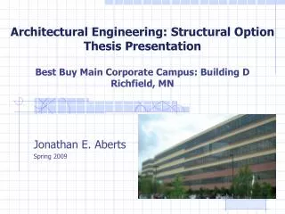
Architectural Engineering: Structural OptionThesis PresentationBest Buy Main Corporate Campus: Building DRichfield, MN Jonathan E. Aberts Spring 2009
Presentation Outline • Introduction • Building description • Existing structural conditions • Project Proposal • Building Redesign • Columns • PT floor system • Lateral system • Foundation • Cost Comparison • Architectural Comparison • Conclusions
Building Name: Best Buy Main Corporate Building Location: Richfield, MN Function: Office building Occupants: Best Buy corporate employees Architects: Perkins & Will (www.perkinswill.com) Minneapolis, MN Engineers: Opus Northwest (www.opuscorp.com) Minnetonka, MN CM: Opus Northwest Chris Johnson Introduction
Building Description Architecture • Precast curtain wall • Ribbon windows • Curtain wall consists of 6” architectural precast panels tied into the steel structure • Prefinished aluminum closure panel holds the ribbon of windows on each floor
Structural System Floor System • Composite beam framing system • 6¼” slab, 3” 20 gauge deck and 3¼” lightweight concrete • Spray on fireproofing
Structural System Lateral System • Braced frame consist of 3 - W14 columns spliced together at the 3rd and 5th floors • Heavier beams, W16x57
Project Proposal Proposed Solution: • Redesign Best Buy Corporate Building D as a full concrete system • Floor system will be redesigned post-tensioned slab with beams • Columns will also be redesigned into concrete • Lateral bracing system will be shear walls • Goal is to allow for a larger bay size in the short direction of the building • Cost Comparison of structural system • The impact of the change in architecture on the tenant and rentable area
Project Proposal Solution Method: • Utilize ACI 318-05 Building Code Requirements for Structural Concrete • Utilize ADAPT-PT to design beams and slab • Utilize PCA Column and ETABS to design columns and shear walls • Utilize RS Means Building Construction Cost Data for a structural cost analysis • Compare and contrast new vs. old architecture
Building Redesign • Columns • PT floor system • PT beams • Shear Walls • Foundation
Columns • Design floor layout to support larger bays with fewer columns • PCA Columns aided in design of reinforcement • ETABS used to verify column sizing
Columns • 30”x30” columns requiring 32-#11 vertical reinforcing • 24”x24” columns requiring 28-#11 vertical reinforcing
Post-tensioned Slab • Design post-tensioned slab using ADAPT-PT as an aid • Keep slab thickness close to 8” as recommended by span/depth ratio
Post-tensioned Slab • Unit strip method • Determined a 9.5” slab was required • 2 tendons required for first and last 2 spans • 1 tendon for the remaining spans
Post-tensioned Beams • Design post-tensioned beam using ADAPT-PT as an aid • Keep beam thickness close to 27” as recommended by span/depth ratio
Post-tensioned Beams • 2 different beams had to be designed • 2 span (57’6”,57’6”) • 3 span (42’6”,30’,42’6”) • Designed 28” deep for both spans • 27 tendons needed for 2 span and 19 tendons for 3 span
Lateral System • Redesign braced frames into shear walls while maintaining current location
Lateral System • ETABS assisted in the design • Found that a 12” wall was a sufficient thickness • Boundary elements were designed to fit inside the 12” wall
Foundation • Considered, however, not redesigned • Heavier concrete columns and shear walls • Larger piers and slabs • Stronger concrete
Cost Comparisons • A considerable increase in costs of materials and erection • 38%
Architecture Comparisons • Increased open space bays from 42’6” to 57’6” • No fireproofing • Fewer columns for partitioned rooms to work around
Conclusions • New floor system increased bay sizes without sacrificing ceiling/floor height • Cost of new system far exceeds cost of existing system
Acknowledgements • Thesis Advisors: • Dr. Thomas E. Boothby • Industry Contacts: • Gary R. Strand, P.E. - Simpson Gumpertz & Heger • David B. Smith, P.E. - Holbert Apple Associates • Richard Apple, P.E. - Holbert Apple Associates • Other Mentors: • Professor M. Kevin Parfitt • Professor Moses Ling