Download
1 / 29
290 likes | 310 Views
Explore carrier modeling in semiconductors, Boltzmann approximation, equilibrium carrier concentrations, and intrinsic carrier concentration relationships in silicon. Understand carrier action including drift, diffusion, and recombination-generation processes.

E N D
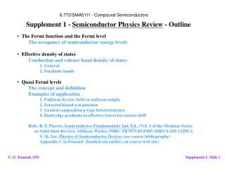
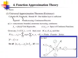
Chapter 2 Carrier Modeling Boltzmann Approximation of Fermi Function • The Fermi Function that describes the probability that a state at energy E is filled with an electron, under equilibrium conditions, is already given as: • Fermi Function can be approximated as: if E – EF > 3kT if EF– E > 3kT
Chapter 2 Carrier Modeling Ec 3kT EF in this range 3kT Ev Nondegenerately Doped Semiconductor • The expressions for n and p will now be derived in the range where the Boltzmann approximation can be applied: • The semiconductor is said to be nondegenerately doped(lightly doped) in this case.
Chapter 2 Carrier Modeling Degenerately Doped Semiconductor • If a semiconductor is very heavily doped, the Boltzmann approximation is not valid. • For Si at T = 300 K,Ec-EF < 3kT if ND > 1.6 1018cm–3EF-Ev < 3kT if NA > 9.1 1017cm–3 • The semiconductor is said to be degenerately doped (heavily doped) in this case. • ND = total number of donor atoms/cm3 • NA = total number of acceptor atoms/cm3
Chapter 2 Carrier Modeling Equilibrium Carrier Concentrations • Integrating n(E) over all the energies in the conduction band to obtain n (conduction electron concentration): • By using the Boltzmann approximation, and extending the integration limit to , • NC = “effective” density of conduction band states • For Si at 300 K, NC = 3.22 1019 cm–3
Chapter 2 Carrier Modeling Equilibrium Carrier Concentrations • Integrating p(E) over all the energies in the conduction band to obtain p (hole concentration): • By using the Boltzmann approximation, and extending the integration limit to , • NV = “effective” density of valence band states • For Si at 300 K, NV = 1.83 1019 cm–3
Chapter 2 Carrier Modeling Intrinsic Carrier Concentration • Relationship between EF and n, p : • For intrinsic semiconductors, where n = p = ni, • EG : band gap energy
Chapter 2 Carrier Modeling Intrinsic Carrier Concentration
Chapter 2 Carrier Modeling Alternative Expressions: n(ni, Ei) and p(ni, Ei) • In an intrinsic semiconductor, n = p = ni and EF = Ei, where Ei denotes the intrinsic Fermi level.
Chapter 2 Carrier Modeling Ec EG = 1.12 eV Ei Ev Si Intrinsic Fermi Level, Ei • To find EF for an intrinsic semiconductor, we use the fact that n = p. • Ei lies (almost) in the middle between Ec and Ev
Chapter 2 Carrier Modeling Example: Energy-Band Diagram • For Silicon at 300 K, where is EF if n = 1017 cm–3 ? • Silicon at 300 K, ni= 1010 cm–3
Chapter 2 Carrier Modeling Charge Neutrality and Carrier Concentration • ND: concentration of ionized donor (cm–3) • NA: concentration of ionized acceptor (cm–3)? • + • – • Charge neutrality condition: • Ei quadratic equation in n
Chapter 2 Carrier Modeling Charge-Carrier Concentrations • The solution of the previous quadratic equation for n is: • New quadratic equation can be constructed and the solution for p is: • Carrier concentrations depend on net dopant concentration ND–NAor NA–ND
Chapter 2 Carrier Modeling Ec 400 K 300 K EF (donor-doped) Ei EF (acceptor-doped) 400 K 300 K Net dopant concentration (cm–3) Ev 1013 1014 1015 1016 1017 1018 1019 1020 Dependence of EF on Temperature
Phosphorus-doped Si Chapter 2 Carrier Modeling Carrier Concentration vs. Temperature ND = 1015 cm–3 • n : number of majority carrier • ND : number of donor electron • ni : number of intrinsic conductive electron
Chapter 3 Carrier Action Carrier Action • Three primary types of carrier action occur inside a semiconductor: • Drift: charged particle motion in response to an applied electric field. • Diffusion: charged particle motion due to concentration gradient or temperature gradient. • Recombination-Generation:a process where charge carriers (electrons and holes) are annihilated (destroyed) and created.
Chapter 3 Carrier Action 2 3 1 electron 4 5 Carrier Scattering • Mobile electrons and atoms in the Si lattice are always in random thermal motion. • Electrons make frequent collisions with the vibrating atoms. • “Lattice scattering” or “phonon scattering” increases with increasing temperature. • Average velocity of thermal motion for electrons: ~1/1000 x speed of light at 300 K (even under equilibrium conditions). • Other scattering mechanisms: • Deflection by ionized impurity atoms. • Deflection due to Coulombic force between carriers or “carrier-carrier scattering.” • Only significant at high carrier concentrations. • The net current in any direction is zero, if no electric field is applied.
Chapter 3 Carrier Action 2 3 1 4 electron 5 E Carrier Drift • When an electric field (e.g. due to an externally applied voltage) is applied to a semiconductor, mobile charge-carriers will be accelerated by the electrostatic force. • This force superimposes on the random motion of electrons. F=–qE • Electrons drift in the direction opposite to the electric fieldèCurrent flows. • Due to scattering, electrons in a semiconductor do not achieve constant velocity nor acceleration. • However, they can be viewed as particles moving at a constant average drift velocity vd.
Chapter 3 Carrier Action Drift Current vdt All holes this distance back from the normal plane vdtA All holes in this volume will cross the plane in a time t pvdt A Holes crossing the plane in a time t q pvdt A Charge crossing the plane in a time t qpvd A Charge crossing the plane per unit time I (Ampere) Þ Hole drift current qpvdCurrent density associated with hole drift current J (A/m2)
Chapter 3 Carrier Action Hole and Electron Mobility • For holes, • Hole current due to drift • Hole current density due to drift • In low-field limit, • μp : hole mobility • Similarly for electrons, • Electron current density due to drift • μn : electron mobility
Chapter 3 Carrier Action Drift Velocity vs. Electric Field • Linear relation holds in low field intensity, ~5103 V/cm
Chapter 3 Carrier Action Hole and Electron Mobility has the dimensions ofv/E: Electron and hole mobility of selected intrinsic semiconductors (T = 300 K)
Chapter 3 Carrier Action RL RI Temperature Effect on Mobility • Impedance to motion due to lattice scattering: • No doping dependence • Decreases with decreasing temperature • Impedance to motion due to ionized impurity scattering: • increases with NA or ND • increases with decreasing temperature
Chapter 3 Carrier Action Temperature Effect on Mobility • Carrier mobility varies with doping: • Decrease with increasing total concentration of ionized dopants. • Carrier mobility varies with temperature: • Decreases with increasing T if lattice scattering is dominant. • Decreases with decreasing T if impurity scattering is dominant.
Chapter 3 Carrier Action Conductivity and Resistivity JN|drift = –qnvd = qnnE JP|drift= qpvd = qppE Jdrift = JN|drift + JP|drift=q(nn+pp)E = E • Conductivity of a semiconductor: =q(nn+pp) • Resistivityof a semiconductor: =1 /
Chapter 3 Carrier Action Resistivity Dependence on Doping • For n-type material: • For p-type material:
Chapter 3 Carrier Action Example • Consider a Si sample at 300 K doped with 1016/cm3 Boron. What is its resistivity? • NA = 1016/cm3 , ND = 0 • (NA >> NDp-type) • p 1016/cm3, n 104/cm3
Chapter 3 Carrier Action Example • Consider a Si sample doped with 1017cm–3 As.How will its resistivity change when the temperature is increased from T = 300 K to T = 400 K? • The temperature dependent factor in (and therefore ) is n. • From the mobility vs. temperature curve for 1017cm–3, we find that n decreases from 770 at 300 K to 400 at 400 K. • As a result, increases by a factor of:
Chapter 2 Carrier Action Homework 2 • 1.a. (4.2) • Calculate the equilibrium hole concentration in silicon at T = 400 K if the Fermi energy level is 0.27 eV above the valence band energy. • 1.b. (E4.3) • Find the intrinsic carrier concentration in silicon at:(i) T = 200 K and (ii) T = 400 K. • 1.c. (4.13) • Silicon at T = 300 K contains an acceptor impurity concentration of NA = 1016 cm–3. Determine the concentration of donor impurity atoms that must be added so that the silicon is n-type and the Fermi energy level is 0.20 eV below the conduction band edge. • 2. (4.17) • Problem 3.6, Pierret’s “Semiconductor Device Fundamentals”. • Deadline: 2 February 2011, at 10:30 (Wednesday).