Download
1 / 20
391 likes | 1.25k Views
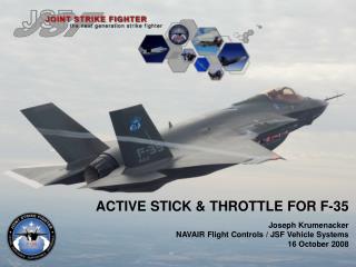
ACTIVE STICK & THROTTLE FOR F-35 Joseph Krumenacker NAVAIR Flight Controls / JSF Vehicle Systems 16 October 2008. Intro.

E N D
ACTIVE STICK & THROTTLE FOR F-35 Joseph Krumenacker NAVAIR Flight Controls / JSF Vehicle Systems 16 October 2008
Intro Joe Krumenacker holds a BS in Aerospace & Mechanical Engineering from the University of Notre Dame, and previously worked for Grumman in aerodynamics, flight controls and flight test on the X-29 and F-14 programs. He joined the NAVAIR Flight Controls Branch in 1996 and has worked on the Joint Strike Fighter since 1999. He currently leads the JSF Program Office’s Vehicle Control Integration team.
ACTIVE STICK & THROTTLE FOR F-35 Joseph Krumenacker NAVAIR Flight Controls / JSF Vehicle Systems 16 October 2008
JSF Active Inceptor System (AIS) Presentation Overview • Why & What of Active Inceptors: • JSF Inceptor Overview & Architecture • Reconfiguration for AIS Degraded Modes • AIS Specification Issues • How have Active Inceptors been put to use: • Current Uses of Active Capability • Jetborne Advanced Modes Using Active Capability • Lessons Learned • Conclusions
Active Inceptor Overview • As a system the AIS is partitioned into the following major elements • Electronics • Processor modules, motor drives, interfaces to FCC / grips • Mechanics • Gimbal assemblies, bearings, housings, seals & mountings • Electromechanical • Servo Actuator Units (SAUs), sensors Mechanics Electronics Electromechanical
Why Were Active Inceptors Chosen? • Design Flexibility for STOVL Advanced Control Law • JSF specification prohibits the use of a third inceptor and requires a pilot interface that minimizes both pilot workload and cognitive error potential. • Throttle Back-drive Capability • PA Approach Power Compensation (Auto-Throttle) • UA Speed Hold Modes • STOVL Performance Protection & Auto-Deceleration Modes • Commonality Between CTOL, STOVL and CV Variants • Active Stick & Throttle Had Already Been Proven on X-35 Demonstrator • X-35 active throttle had a separate nozzle control lever
AIS Installation Overview SideStick (ASSCA) Inceptor Control Unit (ICU) FWD • All JSF variants (CTOL, STOVL & CV) use identical AIS hardware & software. • AIS is provided as a complete system by BAE, Rochester UK • Stick & Throttle grips not procured as part of AIS. Throttle (ATQA)
F-35 AA-1 Cockpit Active Side-Stick (approx. ±6 deg deflection) Active Throttle (9-inch linear deflection)
Inceptor Characteristics • Three Axes of Control: Stick Pitch, Stick Roll, Throttle • Each Axis contains duplex 28V electric motor drives connected to grip interface by mechanical linkages • Each Axis contains triplex force and position sensors • Stick Axes contain mechanical springs for backup mode • Grips (and various HOTAS switches) are supplied by separate vendor, but are qualified for flight together with the stick & throttle.
VMC & Inceptor Architecture AIS ICU SideStick (duplex motor interface) VMC A Chan A Pitch Axis (IEEE1394 network) VMC B Chan B Roll Axis VMC C Chan C Throttle Fore/Aft Each Vehicle Management Computer (VMC) Contains: CLAW Application which determines inceptor force gradients and other features FCRM Application to manage ICU health & failure reports and to select triplex inceptor position & forces for CLAW input Inceptor Control Unit (ICU) performs: Motor Drive Loop Closure & Control Failure Management Mode Control Initiated Built-In Test (triplex grip force & position feedbacks)
AIS Modes & Fault Accommodation • Each Inceptor has three primary control modes: • Active: sensed grip force is used to actively position the inceptor according to the programmed force vs. position characteristics • Flight Control Laws use inceptor position as pilot command • Passive: motor drives disengaged, stick springs provide fixed linear force gradient, throttle has fixed friction & no detents • Used upon unrecoverable error with motor drives • Flight Control Laws use stick forces and throttle position as pilot command • Both stick axes will maintain like mode (if one axis downgrades passive mode, other axis will be place passive mode) • Jammed: inceptor position is fixed • automatically detected by software • Flight Control Laws use inceptor force as pilot command • jammed throttle requires some Control Law reconfiguration
Programmable Inceptor Active Mode Characteristics: force gradients/ramps forward & aft end stops variable damping force gates & soft-stops (e.g AB) pilot-adjustable friction force (throttle) force detents (STOVL) position back-drive (auto-throttle modes) Inceptor Specification Issues: force capability (static and dynamic) force accuracy/variability velocity capability motor drive redundancy electronics redundancy force sensor null drift & sensor noise characteristics passive mode centering (stick) passive mode breakout and force gradients (stick) Active Inceptor Requirements & Specification Issues Blue shaded items are less configuration-dependent than others and could benefit from industry-wide specifications or guidance.
How Is Active Capability Currently Used? • Throttle: • Variable aft & forward end-stops (e.g. STOVL mode is different from CTOL mode) • AB gate (when STOVL system is not deployed) • Launch gate (CV only) • STOVL center detent (zero commanded acceleration) • STOVL on-ground power braking force gradient • Back-drive • Auto-Throttle Approach (all variants) • STOVL Decel-to-Hover
How Is Active Capability Currently Used? • Stick: • Tailored STOVL pitch force characteristics • wingborne vs. jetborne variations • forward soft-stop(s) for vertical landing sink speed • Pitch force feedback at higher AOA • Roll force tailoring: left vs. right • Roll force tailoring: CTOL vs. STOVL • Increased force breakout for CV launch (pitch & roll)
Background: F-35B Jetborne Control Strategy Longitudinal Right-Hand Inceptor (RHI) provides height rate control (zero force commands altitude hold) Left-Hand Inceptor (LHI) provides fore/aft acceleration control (with speed hold function on center detent) Lateral Right-Hand Inceptor (RHI) provides bank angle control to give lateral acceleration • Full matrix of STOVL tasks can be flown by using only the two primary inceptors in a consistent manner throughout the flight envelope. • Nozzle / thrust vector control not required in flight • Cognitive error potential minimized by consistent inceptor functionality • HOTAS functions can be added to provide additional hover control options
Further Advancements Using Active Inceptors: TRC Mode TRC = Translational Rate Command LHI (Throttle) Characteristics Lateral RHI (Stick) Characteristics LHI Force (lbs) RHI Force (lbs) Disengage Stop Disengage Stop Disengage Stop Disengage Stop 20 20 10 10 Decel Cmd Accel Cmd Bank Cmd Bank Cmd RIGHT LEFT 5 4 4 5 1 LHI Displacement (inches) 1 RHI Displacement (deg) AFT FWD Velocity Command (kts) Velocity Command (kts) 10 10 10 10 • Engage / Disengage via HOTAS Switch • Velocity Trim via Speedbrake switch • Disengage via Force Breakout • Disengage via Paddle Switch
Potential Option for Longitudinal Stick: Height “Gripper” • Proposed Change to Jetborne Height Axis: Pitch Stick would command altitude acceleration instead of the baseline altitude rate. • releasing the stick would no longer command zero sink rate (altitude-hold), so some other means of low-workload height hold was required • solution was a pilot-engageable “gripper” mode, in which an altitude-hold augmentation could be quickly engaged and disengaged • with gripper engaged, longitudinal stick breakout force is significantly increased to prevent inadvertent disengagement • Altitude Rosette is Boxed on Engagement • Manual Disengage to start descent rate • Pros • Hover stick force is “significantly higher” and provides pilot direct tactile feedback and confirmation that the flight control system is in control of height axes • Push through or paddle off to begin vertical landing • Cons • Remembering to select height hold • More buttons required Boxed Altitude Engaged with S-5 switch Altitude Gripper Breakout: +/- 20 lbs - or - NWS Button
AIS Lessons Learned • Level 1 flying qualities for precise STOVL tasks are possible using a small, limited-displacement stick, due to the ability to set jetborne-specific stick characteristics without compromising wingborne flying qualities. • Passive and jammed modes can be accommodated with only minor flying qualities degradations • throttle control in jammed mode perhaps the greatest challenge • Inceptor back-drive capability can be used to provide critical insight and training to the pilot in a very intuitive manner • power approach auto-throttle as a training aid • STOVL auto-decel and performance deficit protection • (potential) high AOA cueing
Conclusions • JSF is committed to use of active inceptor system (AIS) for all three aircraft variants – production-representative AIS has been flying on AA-1 aircraft since December 2006. • AIS has provided a valuable level of design flexibility both for the existing vehicle control laws and for the resolution of any yet unknown flying qualities shortcomings. • AIS team has been challenged by environmental requirements for force sensors, and has worked hard to ensure force feel characteristics and redundancy management meet vehicle needs.