Flight Instrument Systems
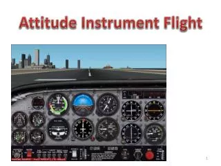
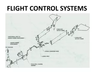
Flight Instrument Systems. Gyroscopic Flight Instruments. Attitude Indicator Heading Indicator Turn Coordinator Gyros are mounted on gimbals which allow the plane to move about the gyro which remains fixed in space. Fundamental Concepts.

Flight Instrument Systems
E N D
Presentation Transcript
Gyroscopic Flight Instruments • Attitude Indicator • Heading Indicator • Turn Coordinator • Gyros are mounted on gimbals which allow the plane to move about the gyro which remains fixed in space
Fundamental Concepts • Rigidity in Space - a wheel with a heavily weighted rim spun rapidly tends to remain fixed in the plane in which it is spinning • Precession - when an outside force is applied the gyro responds as if the force had been applied at a point 900 further around in the direction of rotation
Pendulous Vanes • Open and close to help keep the gyro parallel to the ground • Act on the attitude indicator in an undesirable way during turns do to centrifugal force • Errors are at a maximum in a 1800 turn, no more than 50 of bank
Tumbling • Old attitude indicators would precess rapidly or tumble if you exceeded 1000 or 600 of pitch • Often these attitude indicators had a caging device to right them
Heading Indicators • Must be aligned with the magnetic compass to make it work (Free Gyro) • Must be checked approximately every 15 minutes • A heading indicator with a north seeking system is called a slaved gyro.
Turn Indicators • Standard rate turn is 30 • A 3600 turn takes 2 minutes • To determine the angle of bank required to make a standard rate turn take the (true airspeed in Knots divided by 10) + 5 • At 100 Knots it is approximately 150
Turn Instruments • Turn coordinator • Rate of roll • Rate of turn • Turn and slip indicator • Rate of turn only • Inclinometer
Slip and Skid • Slip - rate of turn is too slow for the bank and the ball moves to the inside of the turn • Skid - rate of turn is too great for the angle of bank and the ball moves to the outside of the turn
Instrument Checks • With the power off, warning flags display OFF indications • Inclinometer full of fluid and ball at lowest point • Turn on master and listen for grinding noise in electric gyros • After starting check ammeter
Instrument Checks • Listen for noise from vacuum gyros • If you think you hear noise, shut off the engine and listen to the gyros spin down • It can take 5 minutes for the gyros to reach full operating speed
Instrument Checks • While taxing out, the turn coordinator and heading indicator should indicate a turn in the correct direction • The ball should swing to the outside in turns • Align the heading indicator with the magnetic compass during runup and check again before takeoff
Magnetic Compass • Errors • Variation - the angular difference between the true and magnetic pole • Deviation - errors due to magnetic interference with the metal components of the aircraft • Magnetic dip - the compass tries to point down deep inside the earth
Pitot Static Instruments • Airspeed Indicator • Vertical Speed Indicator • Altimeter
Airspeed Indicator VSO VNE VNO VFE
Colored Arcs • Yellow - operate in the caution area only in smooth air • Green - normal operating range • White - full flap operating range
Types of Airspeeds • Indicated - displays the speed of your plane. It is the basis for determining your aircraft performance • Calibrated is indicated corrected for installation and instrument error • Equivalent airspeed is calibrated airspeed corrected for adiabatic compressible flow at a particular altitude
Types of Airspeeds • True Airspeed is the actual speed your airplane moves through the air. The calibrated airspeed corrected for density altitude • Mach is the ratio of the aircraft’s true speed to the speed of sound
Types of Altitude • Indicated - is what you read on the altimeter • Pressure - is displayed when you have the altimeter set to 29.92. It is the vertical distance above the standard datum plane • Density - pressure corrected for nonstandard temperature
Types of Altitude • True - is the actual height of an object above mean sea level. • Absolute - is the actual height of the aircraft above the earth’s surface
ISA • International Standard Atmospheric Sea Level - 150 C - 29.92 in HG • Before IFR flight the altimeter set to the current altimeter setting should be within 75 feet of the actual elevation
Vertical Speed Indicator • Displays rate and trend information • 6-9 second delay • Gives erratic readings during turbulence or when applying abrupt control inputs • Not setting before starting engines and use that setting for zero • Not legally required for IFR flight
Pitot Static System Ram air inlet Drain hole
System Errors • Can be caused by blockage of the pitot tube, static port or both • Blockages can be caused by moisture, ice, dirt or even insects • Use pitot tube cover when parked • Use pitot heat when flying in visible moisture
Pitot Blockage • Ram air inlet clogged, drain hole open pressure in line to airspeed indicator drops to zero, airspeed indicator indicates 0 • Ram air inlet clogged, drain hole clogged, air trapped in line, airspeed indicator does not react to changes in speed but altitude like an altimeter
Static Blockage • Airspeed indicator will continue to react to changes in airspeed but they will not be accurate • Altimeter will freeze in place • VSI will freeze at zero • Use alternate static source or break glass in VSI