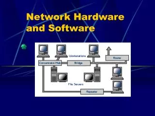
Network Hardware and Software
Network Hardware and Software. ECE 544: Computer Networks II Spring 2014 Dr. Reininger. Part I: What’s inside a router?. Router Architecture (Functional View). IP Router Architecture: An Overview, James Aweya , Nortel Networks. Router Architecture (Component View). Input Ports.

Network Hardware and Software
E N D
Presentation Transcript
Network Hardware and Software ECE 544: Computer Networks II Spring 2014 Dr. Reininger
Router Architecture (Functional View) IP Router Architecture: An Overview, James Aweya, Nortel Networks
Router Table Lookup • Search through the routing table, looking for a destination entry that matches the destination address of the datagram, or a default route if the destination entry is missing. • Backbone routers need to perform millions of lookups per second. • Desired for the input port processing to be able to process at line speed, that is lookup can be done in less than the time needed to receive a packet at the input port. • In this case, input processing of a received packet can be completed before the next receive operation is complete. • OC-48 link runs at 2.5Gbps. With a 256 byte long packet -> ~ 1 million lookups a second.
Routing Table Data Structure • Linear search through a large routing table is impossible. • Store the routing table entries in a tree data structure. • Each level in the tree can be thought of as corresponding to a bit in the destination address. • To lookup an address, start at the root node of the tree. If the first address bit is a zero, then the left subtree will contain the routing table entry for destination address; otherwise it will be in the right subtree. • The appropriate subtree is then traversed using the remaining address bits – if the next address bit is a zero the left subtree of the initial subtree is chosen; otherwise, the right subtree of the initial subtree is chosen. • In this manner, one can lookup the routing table entry in N steps, where N is the number of bits in the address.
Increasing Lookup Speed • Even with N=32 steps, the lookup speed of binary search is not fast enough for today’s backbone routing requirements. • Assuming a memory access at each step, less than a million address lookups/sec could be performed with 40ns memory access times. • Several techniques can be used to increase lookup speed: • Router explicitly checks each incoming packet against a table of all of the router’s addresses to see if there is a match. Routing table is never checked for local traffic (packets destined to the router’s network). • Content addressable memories (CAMs) allow a 32-bit IP address to be presented to the CAM, which then returns the content of the routing table entry for that address in essentially constant time. • Caching recently accessed routing table entries. • For an OC-3 speed link, approximately 256,000 source-destination pairs might be seen in one minute in a backbone router. • Faster data structures which allow routing table entries to be located in log(N) steps. [Waldvogel 1997] • Routing table compression techniques [Degemark 1997] • Exploit the sparseness of actual entries in the space of all possible routing table entries. • Hardware techniques (higher performance at lower cost, but less flexible)
First Generation IP Routers:Bus-based router architecture IP Router Architecture: An Overview, James Aweya, Nortel Networks
Improvement to first generation:Route cache in the network interface Maintain a very fast access subnet of the routing topology information.
Second Generation Router:Multiple Parallel Forwarding Engines IP Router Architecture: An Overview, James Aweya, Nortel Networks
Third Generation:Switched-based IP Router Architecture IP Router Architecture: An Overview, James Aweya, Nortel Networks
Limitation of Route Caching • “Demand caching” schemes subjected to cache misses • Default to classical software-based route lookup (“slow path”). • Routing changes invalidate the cache • Enterprise backbone and public networks subjected to highly random traffic patterns and frequent topology changes eliminate the benefit of route caching.
Overcoming Cache Churn • Use a forwarding database in each network interface which mirrors the entire content of the IP routing table maintained by the CPU • Eliminates the cache and the “slow path”. • Offers significant benefits in terms of performance, scalability, network resilience and functionality, particularly in large complex networks with dynamic flows. • Accommodate network dynamics of short flows associated with Web-based applications and interactive type sessions.
Switched-based Router with fully-distributed processors IP Router Architecture: An Overview, James Aweya, Nortel Networks
IP Router Layer 2/3 entities IP Router Architecture: An Overview, James Aweya, Nortel Networks
IP Router functional partitioning IP Router Architecture: An Overview, James Aweya, Nortel Networks
Fast Path or Slow Path? IP Router Architecture: An Overview, James Aweya, Nortel Networks
Distributed Router Architecture Functional Diagram IP Router Architecture: An Overview, James Aweya, Nortel Networks
Address lookup and forwarding IP Router Architecture: An Overview, James Aweya, Nortel Networks
IP Packet Router Lifecycle IP Router Architecture: An Overview, James Aweya, Nortel Networks
Forwarding databases for Future Internet Services • Non-SQL DB • GET/SET KVPs • Content Routing lookup as Map-Reduce computation • REDIS • Hardware: • 4 GB 1.7 GHz DDR3 RAM • i7 dual core 1.7 GHz with 4 MB shared L3 Cache • 128 GB Flash storage • Operating System: Ubuntu 13.04 • SET: 403.1 KRPS (kilo requests per second) • GET: 508.4 KRPS • 16 MB/MKVPs (encoded into 1,000 hashes of 1,000 sub-keys each)
Shared Memory Switch Fabric IP Router Architecture: An Overview, James Aweya, Nortel Networks
Distributed Output Buffered Switch Fabric IP Router Architecture: An Overview, James Aweya, Nortel Networks
Space Division Switch Fabric IP Router Architecture: An Overview, James Aweya, Nortel Networks
Where does queuing occur? • Packet queues can form at both the input ports and the output ports. • As queues grow larger, the router’s buffer space will eventually be exhausted and packet loss will occur. • The actual location of packet loss (either at input or output port queues) will depend on the traffic load, the relative speed of the switching fabric and the line speed.
Output Queuing (OQ) • 100% throughput • Internal speedup of N • Impractical for large N Output 1 Input 1 3 Output 2 Input 2 3 Output 3 Input 3 3 Output 4 Input 4 3
Input Queuing (IQ) • Easy to implement • HOL Blocking, throughput 58.6% Input 1 Output 1 1 2 Head of Line Blocking Input 2 3 Output 2 2 Input 3 Output 3 4 3 Input 4 Output 4 4 2
Reducing the effects of HOL blocking • Increase the speed of the I/O channel (i.e. speed up the switch fabric) • Under certain assumptions on traffic statistics a speed up (ratio of the switch fabric bandwidth and the bandwidth of the input links) of 4 or 5 leads to 99% throughput. • Recently, a speedup as low as 2 may be sufficient to obtain performance comparable to output buffered switches.
1 1 1 1 2 2 2 2 3 3 3 3 4 4 4 4 Virtual Output Queuing (VOQ) • Virtual Output Queuing (VOQ) • Overcome HOL blocking • No speedup requirement • Need scheduling algorithms to resolve contention • Complexity • Performance guarantee
Terabit and Petabit Packet Switching (TPS and PPS) • Two main transmission/switching technologies • optical-based • advantage: data carrying capacity and longer transmission distances (>1km) • electrical-based • more suited to short distance, e.g. 10GbASE-T is capable of 10 Gb/s over distances of less than 100m • lower cost, higher density, easier control of switching cross points. 10GbASE-T is highly cost competitive for interconnection within data centers. • Cabling uses four pairs of wires in parallel with each pair transmitting at either 0.25 Gbps for 1 GbASE-T or 2.5 Gbps for 10 GbASE-T. • Ethernet at 1 Gb/s and beyond uses both • Electrical allows higher density of crosspoints allow much more capable switch in terms of number of input and output ports. • Multistage Interconnection Networks (MIN) and memory elements are used to construct larger switches • Optical solutions lack fast all-optical data storage for switching and data processing, this necessitating a conversion to electrical signals. • Optical Ethernet does not lend itself to carrier sensing and is often deployed in a point-to-point manner without multiaccessing.
Terabit and Petabit Packet Switching (TPS and PPS) • Content Distribution Service • 100 Mbps multimedia streams to subscribers • 100,000 subscribers with 1 Gbps access -> 100 Tbps • Core switch requires 5,000 10 Gbps ports assuming a 20:1 access switch concentration ratio (20 1 Gbps input lines at the access switch concentrate into 1 10 Gbps input line at the core switch) • Assuming a 1:1 fan in/out for the core switch, the core switch requires 10,000 ports • If we use modules of 100 inputs each, the core switch consists of 100 modules
Terabit and Petabit Packet Switching (TPS and PPS) • Data center LAN motivation example • GbE Host Bus Adapters (HBA) is giving way to 10 GbENICs • 100 x 10 GbE = 1 TbE • After aggregation data can be transported over short distances of less than 30m to end-of-row core switches • PPS needed for interconnecting LANs in data centers.
Router with 10 GbE ports and three physical layer module types http://en.wikipedia.org/wiki/10-gigabit_Ethernet