Download
1 / 14
140 likes | 234 Views
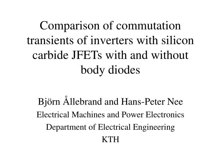
Comparison of commutation transients of inverters with silicon carbide JFETs with and without body diodes. Björn Ållebrand and Hans-Peter Nee Electrical Machines and Power Electronics Department of Electrical Engineering KTH.

E N D
Comparison of commutation transients of inverters with silicon carbide JFETs with and without body diodes Björn Ållebrand and Hans-Peter Nee Electrical Machines and Power Electronics Department of Electrical Engineering KTH
SiC has approximately ten times higher critical electric field compared to Si. This makes SiC attractive for majority carrier (uni-polar) devices. For bi-polar devices the large band gap will lead to high losses. This means that a SiC IGBT will only be interesting for the highest voltage levels. Background I
There is problems with manufacturing SiC MOSFETs. Therefore the interest has shifted to SiC JFETs. There are different ways of designing SiC JFETs. Buried gate JFETs and Vertical JFETs. Background II
Different SiC JFET designs VJFET Bg-JFET
Simulations • Simulations show that it is not much difference between inverters using the different SiC JFETs. • The switching losses will be slightly larger for inverters with SiC JFETs without body diodes.
Short-circuit current Large gate-drain capacitances
Reducing short-circuit currents • Reducing the gate-drain capacitance (redesign of the component). • Increasing the gate voltage to a higher value (may lead to that the component must be redesigned).
New Simulations • In simulations with the gate-drain capacitance lowered by a factor of two, the switching losses were reduced.
Conclusions I • Using an inverter with only SiC JFETs is possible. • Using different SiC JFETs will not affect performance that much. • A drawback is that short-circuit currents will occur and this increases the switching losses. • The short-circuit currents can be reduced by different means.
Conclusions II • The gate-drain capacitance has to be reduced. • Or a higher gate voltage needs to be used.
Future Work • Investigate how the short-circuit current will be for larger devices. • How will the stray inductance affect this short-circuit current.


![G5 - ELECTRICAL PRINCIPLES [3 exam questions - 3 groups]](https://cdn0.slideserve.com/382273/g5-electrical-principles-3-exam-questions-3-groups-dt.jpg)


![SUBELEMENT T5 [4 Exam Questions - 4 Groups]](https://cdn0.slideserve.com/1420383/subelement-t5-4-exam-questions-4-groups-dt.jpg)