Download
1 / 20
200 likes | 311 Views
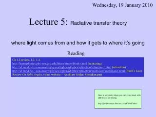
Wednesday, 19 January 2010. Lecture 5: Radiative transfer theory where light comes from and how it gets to where it’s going. Reading. Ch 1.2 review, 1.3, 1.4 http://hyperphysics.phy-astr.gsu.edu/hbase/atmos/blusky.html (scattering)

E N D
Wednesday, 19 January 2010 Lecture 5: Radiative transfer theory where light comes from and how it gets to where it’s going Reading Ch 1.2 review, 1.3, 1.4 http://hyperphysics.phy-astr.gsu.edu/hbase/atmos/blusky.html (scattering) http://id.mind.net/~zona/mstm/physics/light/rayOptics/refraction/refraction1.html (refraction) http://id.mind.net/~zona/mstm/physics/light/rayOptics/refraction/snellsLaw/snellsLaw1.html (Snell’s Law) Review On Solid Angles, (class website -- Ancillary folder: Steradian.ppt) Here is a website where you can experiment with additive color mixing http://javaboutique.internet.com/ColorFinder/
What was covered in the previous lecture LECTURES Jan 05 1. Intro Jan 07 2. Images Jan 12 3. Photointerpretation • Jan 14 4. Color theory previous • Jan 19 5. Radiative transfer today Jan 21 6. Atmospheric scattering Jan 26 7. Lambert’s Law Jan 28 8. Volume interactions Feb 02 9. Spectroscopy Feb 04 10. Satellites & Review Feb 09 11. Midterm Feb 11 12. Image processing Feb 16 13. Spectral mixture analysis Feb 18 14. Classification Feb 23 15. Radar & Lidar Feb 25 16. Thermal infrared Mar 02 17. Mars spectroscopy (Matt Smith) Mar 04 18. Forest remote sensing (Van Kane) Mar 09 19. Thermal modeling (Iryna Danilina) Mar 11 20. Review Mar 16 21. Final Exam • Friday’s lecture: • Color and the spectrum • Color perception • Additive & subtractive color mixing • Ternary diagrams and color transformations • Selective absorption of light • Today • The atmosphere and energy budgeting • Modeling the atmosphere • Radiative transfer equation • “Radiosity” 2
The Electromagnetic Spectrum (review) Units: Micrometer (mm) = 10-6 m Nanometer (nm) = 10-9 m This chart shows the spectrum The Sun Light emitted by the sun This graph is a spectrum 3
Light from Sun – Light Reflected and Emitted by Earth W m-2 μm -1 W m-2μm-1 sr-1 Wavelength, μm The sun is not an ideal blackbody – the 5800 K figure and graph are simplifications 4
Atmospheric Constituents Constant Nitrogen (78.1%) Oxygen (21%) Argon (0.94%) Carbon Dioxide (0.033%) Neon Helium Krypton Xenon Hydrogen Methane Nitrous Oxide Variable Water Vapor (0 - 0.04%) Ozone (0 – 12x10-4%) Sulfur Dioxide Nitrogen Dioxide Ammonia Nitric Oxide All contribute to scattering For absorption, O2, O3, and N2 are important in the UV CO2 and H2O are important in the IR (NIR, MIR, TIR) 6
Solar spectra before and after passage through the atmosphere 7
Modeling the atmosphere To calculate t we need to know how k in the Beer-Lambert-Bouguer Law (called b here) varies with altitude. Modtran models the atmosphere as thin homogeneous layers. Modtran calculates k or b for each layer using the vertical profile of temperature, pressure, and composition (like water vapor). This profile can be measured made using a balloon, or a standard atmosphere can be assumed. Fo is the incoming flux 9
20 15 10 5 0 20 15 10 5 0 Altitude (km) Altitude (km) 0 20 40 60 80 100 -80 -40 0 40 Relative Humidity (%) Temperature (oC) Radiosonde data Mt Everest Mt Rainier 10
Radiant energy – Q (J) - electromagnetic energy Solar Irradiance – Itoa(W m-2) - Incoming radiation (quasi directional) from the sun at the top of the atmosphere. Irradiance – Ig (W m-2) - Incoming hemispheric radiation at ground. Comes from: 1) direct sunlight and 2) diffuse skylight (scattered by atmosphere). Downwelling sky irradiance – Is↓(W m-2) – hemispheric radiation at ground Path Radiance - Ls↑ (W m-2 sr-1 ) (Lpin text) - directionalradiation scattered into the camera from the atmosphere without touching the ground Transmissivity – t- the % of incident energy that passes through the atmosphere Radiance – L (W m-2 sr-1) – directional energy density from an object. Reflectance – r -The % of irradiance reflected by a body in all directions (hemispheric: r·I) or in a given direction (directional: r·I·p-1) Note: reflectance is sometimes considered to be the reflected radiance. In this class, its use is restricted to the % energy reflected. Terms and units used in radiative transfer calculations 0.5º Itoa L Ls↑ Is↓ Ig 11
Radiative transfer equation Parameters that relate to instrument and atmospheric characteristics DN = a·Ig·r + b This is what we want Igis the irradiance on the ground r is the surface reflectance a & b are parameters that relate to instrument and atmospheric characteristics 12
Radiative transfer equation DN = a·Ig·r + b DN = g·(te·r · ti·Itoa·cos(i)/p + te· r·Is↓/p + Ls↑) + o g amplifier gain t atmospheric transmissivity e emergent angle i incident angle r reflectance Itoa solar irradiance at top of atmosphere Ig solar irradiance at ground Is↓ down-welling sky irradiance Ls↑ up-welling sky (path) radiance o amplifier bias or offset 13
Lambert The factor of p Consider a perfectly reflective (r=100%) diffuse “Lambertian” surface that reflects equally in all directions. 14
The factor of p Consider a perfectly reflective (r=100%) diffuse “Lambertian” surface that reflects equally in all directions. If irradiance on the surface is Ig, then the irradiance from the surface is r·Ig = Ig W m-2. The radiance intercepted by a camera would be r·Ig/p W m-2 sr-1. The factor p is the ratio between the hemispheric radiance (irradiance) and the directional radiance. The area of the sky hemisphere is 2p sr (for a unit radius). So – why don’t we divide by 2p instead of p? 15
p/2 p/2 2p 2p ∫ ∫ L sin cos d dw=pL ∫ ∫ sin d dw=2p 0 0 0 0 • Incoming directional radiance L at elevation angle is isotropic • Reflected directional radiance Lcos is isotropic • Area of a unit hemisphere: The factor of p Consider a perfectly reflective (r=100%) diffuse “Lambertian” surface that reflects equally in all directions. 16
Measured Ltoa DN(Itoa) = a Itoa + b Itoa Ltoa=ter (ti Itoa cos(i))/p + te r Is↓ /p+ Ls↑ Itoa cos(i) i Ls↑ (Lp) ti te i e Ig=ti Itoa cos(i) r(ti Itoa cos(i)) /p reflected light r reflectance “Lambertian” surface 17
What was covered in today’s lecture? • The atmosphere and energy budgeting • Modeling the atmosphere • Radiative transfer equation • “Radiosity” 20
What will be covered in next Tueday’s lecture? • Atmospheric scattering and other effects • - where light comes from and how it gets there • - we will trace radiation from its source to camera • - the atmosphere and its effect on light • - the basic radiative transfer equation: DN = a·Ig·r + b Mauna Loa, Hawaii 21