Link Layer Protocols
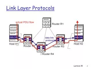
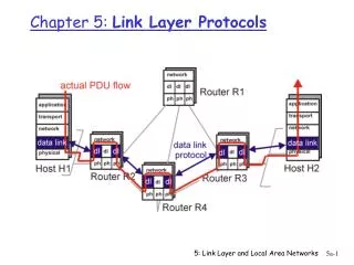
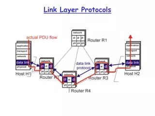
Link Layer Protocols. Link Layer Services. Framing and link access : encapsulate datagram into frame adding header and trailer, implement channel access if shared medium, ‘physical addresses’ are used in frame headers to identify source and destination of frames on broadcast links

Link Layer Protocols
E N D
Presentation Transcript
Link Layer Services • Framing and link access: • encapsulate datagram into frame adding header and trailer, • implement channel access if shared medium, • ‘physical addresses’ are used in frame headers to identify source and destination of frames on broadcast links • Reliable Delivery: • seldom used on fiber optic, co-axial cable and some twisted pairs too due to low bit error rate. • Used on wireless links, where the goal is to reduce errors thus avoiding end-to-end retransmissions
Link Layer Services (more) • Flow Control: • pacing between senders and receivers • Error Detection: • errors are caused by signal attenuation and noise. • Receiver detects presence of errors: • it signals the sender for retransmission or just drops the corrupted frame • Error Correction: • mechanism for the receiver to locate and correct the error without resorting to retransmission
Link Layer Protocol Implementation • Link layer protocol entirely implemented in the adapter (eg,PCMCIA card). Adapter typically includes: RAM, DSP chips, host bus interface, and link interface • Adapter send operations: encapsulates (set sequence numbers, feedback info, etc.), adds error detection bits, implements channel access for shared medium, transmits on link • Adapter receive operations: error checking and correction, interrupts host to send frame up the protocol stack, updates state info regarding feedback to sender, sequence numbers, etc.
Error Detection • EDC= Error Detection and Correction bits (redundancy) • D = Data protected by error checking, may include some header fields • Error detection is not 100%; • protocol may miss some errors, but rarely • Larger EDC field yields better detection and correction
Parity Checking Single Bit Parity: Detect single bit errors Two Dimensional Bit Parity: Detect and correct single bit errors
Checksumming Methods • Internet Checksum: View data as made up of 16 bit integers; add all the 16 bit fields (one’s complement arithmetic) and append the frame with the resulting sum; the receiver repeats the same operation and matches the checksum sent with the frame • Cyclic Redundancy Codes: • Data is viewed as a string of coefficients of a polynomial (D) • A Generator polynomial is chosen (=> r+1 bits), (G) • Divide (modulo 2) the D*2r polynomial by G. Append the remainder (R) to D. Note that, by construction, the new string <D,R> is now divisible exactly by G
CRC Implementation (cont) • The sender carries out on-line, in hardware the division of the string D by the polynomial G and appends the remainder R to it • The receiver divides < D,R> by G; if the remainder is non-zero, the transmission was corrupted • International standards for G polynomials of degrees 8, 12, 15 and 32 have been defined • ARPANET was using a 24 bit CRC for the alternating bit link protocol • ATM is using a 32 bit CRC in ALL 5 • HDLC uses a 16 bit CRC
Multiple Access Links and Protocols Three types of links: (a) Point-to-point (single wire) (b) Broadcast (shared wire or medium; eg, E-net, wireless, etc.) (c) Switched (eg, switched E-net, ATM etc) We start with Broadcast links. Main challenge: Multiple Access Protocol
Multiple Access Control (MAC) Protocols • MAC protocol: coordinates transmissions from different stations in order to minimize/avoid collisions • (a) Channel Partitioning MAC protocols • (b) Random Access MAC protocols • (c) “Taking turns” MAC protocols • Goal: efficient, fair, simple, decentralized
Channel Partitioning MAC protocols • TDM (Time Division Multiplexing): channel divided into N time slots, one per user; inefficient with low duty cycle users and at light load. • FDM (Frequency Division Multiplexing): frequency subdivided.
Channel Partitioning (CDMA) • CDMA (Code Division Multiple Access): exploits spread spectrum (DS or FH) encoding scheme • unique “code” assigned to each user; ie, code set partitioning • Used mostly in wireless broadcast channels (cellular, satellite,etc) • All users share the same frequency, but each user has own “chipping” sequence (ie, code) • Chipping sequence like a mask: used to encode the signal • encoded signal = (original signal) X (chipping sequence) • decoding: innerproduct of encoded signal and chipping sequence (note, the innerproduct is the sum of the component-by-component products) • To make CDMA work, chipping sequences must be chosen orthogonal to each other (i.e., innerproduct = 0)
CDMA (cont’d) CDMA Properties: • protects users from interference and jamming (used in WW II) • protects users from radio multipath fading • allows multiple users to “coexist” and transmit simultaneously with minimal interference (if codes are “orthogonal”)
Random Access protocols • A node transmits at random (ie, no a priory coordination among nodes) at full channel data rate R. • If two or more nodes “collide”, they retransmit at random times • The random access MAC protocol specifies how to detect collisions and how to recover from them (via delayed retransmissions, for example) • Examples of random access MAC protocols: (a) SLOTTED ALOHA (b) ALOHA (c) CSMA and CSMA/CD
Slotted Aloha • Time is divided into equal size slots (= full packet size) • a newly arriving station transmits a the beginning of the next slot • if collision occurs (assume channel feedback, eg the receiver informs the source of a collision), the source retransmits the packet at each slot with probability P, until successful. • Success (S), Collision (C), Empty (E) slots • S-ALOHA is channel utilization efficient; it is fully decentralized.
Slotted Aloha efficiency If N stations have packets to send, and each transmits in each slot with probability p, the probability of successful transmission S is: For a particular node, S= p (1-p)(N-1) For an arbitrary node of the N, S = Prob (only one transmits) = N p (1-p)(N-1) Optimal value of P: P = 1/N For example, if N=2, S= .5 For N very large one finds S= 1/e (approximately, .37)
Pure (unslotted) ALOHA • Slotted ALOHA requires slot synchronization • A simpler version, pure ALOHA, does not require slots • A node transmits without awaiting for the beginning of a slot • Collision probability increases (packet can collide with other packets which are transmitted within a window twice as large as in S-Aloha) • Throughput is reduced by one half, ie S= 1/(2e)
CSMA (Carrier Sense Multiple Access) • CSMA: listen before transmit. If channel is sensed busy, defer transmission • Persistent CSMA: retry immediately when channel becomes idle (this may cause instability) • Non persistent CSMA: retry after random interval • Note: collisions may still exist, since two stations may sense the channel idle at the same time ( or better, within a “vulnerable” window = round trip delay) • In case of collision, the entire pkt transmission time is wasted
CSMA/CD (Collision Detection) • CSMA/CD: carrier sensing and deferral like in CSMA. But, collisions are detected within a few bit times. • Transmission is then aborted, reducing the channel wastage considerably. • Typically, persistent retransmission is implemented • Collision detection is easy in wired LANs (eg, E-net): can measure signal strength on the line, or code violations, or compare tx and receive signals • Collision detection cannot be done in wireless LANs (the receiver is shut off while transmitting, to avoid damaging it with excess power) • CSMA/CD can approach channel utilization =1 in LANs (low ratio of propagation over packet transmission time)
“Taking Turns” MAC protocols • So far we have seen that channel partitioning MAC protocols (TDM, FDM and CDMA) can share the channel fairly; but a single station cannot use it all • Random access MAC protocols allow a single user full channel rate; but cannot share the channel fairly (in fact, capture is often observed) • Also there are “taking turns” protocols...
“Taking Turns” MAC protocols • Taking Turns MAC protocols achieve both fairness and full rate, at the expense of some extra control overhead (a) Polling: a Master station on a LAN in turn “invites” the slave stations to transmit their packets (up to a Max). Problems: Request to Send/Clear to Send overhead, latency, single point of failure (Master) (b) Token passing: the control token is passed from one node to the next sequentially. Can alleviate the latency and improve fault tolerance (in a token bus configuration). Still, elaborate procedures to recover from lost token, etc.
LAN technologies • MAC protocols used in LANs, to control access to the channel • Token Rings: IEEE 802.5 (IBM token ring), for computer room, or Department connectivity, up to 16Mbps; FDDI (Fiber Distributed Data Interface), for Campus and Metro connectivity, up to 200 stations, at 100Mbps. • Ethernets: employ the CSMA/CD protocol; 10Mbps (IEEE 802.3), Fast E-net (100Mbps), Giga E-net (1,000 Mbps); by far the most popular LAN technology