Two-Beam Interference in Optics Applications
Explore the concept of two-beam interference, constructive and destructive superposition, interference terms, measurement techniques like Fizeau fringes, Twyman-Green Interferometer, interferometric microscopy, and film thickness monitoring methods.

Two-Beam Interference in Optics Applications
E N D
Presentation Transcript
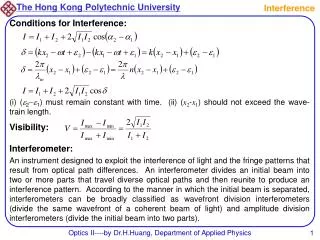
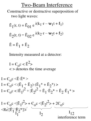
Two-Beam Interference Constructive or destructive superposition of two light waves: Ē1(r, t) = Ē01 e i(k1·r – w1t + f1) Ē2(r, t) = Ē02 e i(k2·r – w2t + f2) Ē = Ē1 + Ē2 Intensity measured at a detector: I = Єoc < Ē2> < > denotes the time average I = Єoc <Ē·Ē* > I = Єoc < (Ē1 + Ē2)·(Ē1* + Ē2*) > I = Єoc < |Ē1|2 + |Ē2|2 + Ē1·Ē2* + Ē2·Ē1* > I = Єoc <|Ē1|2> + Єoc <|Ē2|2> + 2Єoc <Re{Ē1·Ē2*}> I12 I1 I2 interference term
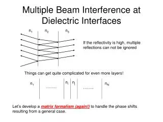
Fizeau Fringes • Fizeau fringes produced by a wedge-shaped film • Difference in film thickness between adjacent • fringes is lo/2n1 Dd = lo/2n1 Fringes of equal thickness (FET) real fringes lo lo S no n1 n2 virtual fringes
Twyman-Green Interferometer • Twyman-Green interferometer used to observe • Fizeau fringes • Equivalent to Michelson interferometer but using • collimated light viewing microscope collimated light lo M ~ normal incidence
Measurement of Optical Flatness • Difference in film thickness between adjacent • fringes is lo/2n1 Dd = lo/2n1 Dd = lo/2n1 lo lo no no n1 n1 n2 n2
Interferometric Microscopy Dd = lo/2n1 lo
Measurement of Film Thickness Dd´/Dd = 2t/lo t = (lo/2) Dd´/Dd Dd´ = t Dd = lo/2 tilted mirror, M2 lo M1 M2´ film thickness, t
Measurement of Film Thickness Dd´/Dd = 2t/lo t = (lo/2) Dd´/Dd • Resolution ~ (550 nm / 2) (1/200) ~ 1.4 nm
Measurement of Film Thickness • Fringe locations move with wavelength • d = (l2/2) Dl / (l1 – l2) Fringes of equal chromatic order (FECO) Dl Monochromator l2 l1 tilted mirror, M2 white light source M1 M2´ film thickness, t
Transparent Films P S lens no n1 d n2 constructive interference: OPD = 2n1dcosqt = mlo destructive interference: OPD = 2n1dcosqt = (m + ½)lo If reflection coefficients (r, r´) are not small then multiple reflections must be added
Multiple-Beam Interference (Etalons) 0 Eo 1 2 3 4 N lens qi tt´r´Eo rEo tt´r´3Eo ... tt´r´5Eo tt´r´7Eo tt´r´r´2(N-1)Eo no r, t ... d n1 qt r´, t´ no ... tt´r´4Eo tt´r´8Eo tt´Eo tt´r´6Eo tt´r´2NEo tt´r´2Eo lens 1 2 3 4 N 0
Multiple-Beam Interference OPD between adjacent rays, D = n1(AB + BC) – no(AD) = 2n1d cosqt Phase difference between adjacent rays, d = kD = (4pn1d/ lo) cos qt D A no C d n1 qt B no ER = rEoeiwt (ray 0) + tt´r´Eoei(wt-d) (ray 1) + tt´r´3Eoei(wt-2d) (ray 2) + ... (rays 3 to N)
Coefficient of Finesse Define coefficient of Finesse, F = 4r2/(1 - r2)2 1 1 + Fsin2(d/2) T = IT/Io = Fsin2(d/2) 1 + Fsin2(d/2) R = IR/Io = Note: R + T = 1 (conservation of energy) Phase difference between adjacent rays, d = (4pn1d / lo) cos qt
Reflectance from a thin film Single layer thin film (n1) on glass (n2=1.5) R(%) d = (4pn1d / lo) cos qt
Thin Film Thickness Monitoring • Variation in R with d can be used to monitor • film thickness (d) during deposition R(%) d = (4pn1d / lo) cos qt
Transparent Films • 2 methods to produce interference in transparent films • Vary the angle of incidence with wavelength fixed • VAMFO (variable angle monochromatic fringe observation) • Vary the wavelength of light with a fixed angle of incidence • CARIS (constant-angle reflection interference spectroscopy) From Ohring, Fig. 6-3, p. 257
Comparison of Film Thickness Measurement Techniques From Ohring, Fig. 6-2, p. 253
Microscopy Conventional microscopy is not sensitive to phase specimens undisturbed light amplitude specimen phase specimen Df
Phase Specimens e.g., a cell (5 mm thick) in aqueous medium R = [(1.335-1.36)/(1.335-1.36)]2 = 0.0086% T = 99.9914% OPD = (1.36 – 1.335)(5 mm) = 0.125 mm = lo/4 Df = 90° t ~ 5 mm n = 1.335 n = 1.36 lo = 500 nm
Differential Interference Contrast (DIC) Microscopy -45° polarizer Wollaston prism objective lens Df sample 2 mm separation between beams condenser lens Wollaston prism 45° polarizer
DIC Microscopy Contrast produced by phase gradients light is blocked light is blocked some light transmitted polarizer phase specimens
Phase Contrast Microscopy transform plane Phase object superposition, Eo + Ed undiffracted wave, Eo E(t) diffracted wave, Ed t particle I(t) surround t
Phase Contrast Microscopy Fritz Zernike: Nobel Prize for Physics, 1953 transform plane phase ring Phase object superposition, Eo + Ed undiffracted wave, Eo E(t) diffracted wave, Ed t I(t) surround particle t