Download
1 / 28
280 likes | 372 Views
Explore the feasibility and validation of two-beam acceleration prototype modules for the CLIC project. Learn about design, procurement status, objectives, and schedules, addressing key feasibility issues. Discover the integration of technical systems for RF production, beam measurement, and acceleration. Follow the progress of prototype modules tested in the lab and industrialization studies.

E N D
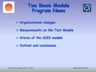
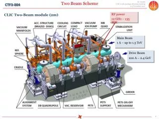
Two-beam acceleration: two-beam prototype validation programG. Riddone in collaboration with N. Gazis, D. Gudkov, A. Solodko(input from CLIC Module WG members) • OUTLINE • Two beam acceleration feasibility issue • Prototypes modules to be tested without RF and beam: design and procurement status, objectives, schedule • Prototypes modules to be tested with RF and beam: design and procurement status, objectives, schedule
CLIC feasibility issues Demonstration of novel scheme of two beam acceleration in compact modules integrating all technical systems for RF production, beam measurement and acceleration including alignment, stabilisation and vacuum at their nominal parameters.
CLIC two-beam modules A. Samoshkin Prototype modules as close as possible to CLIC modules
Steps towards two-beam acceleration modules 2009-2011 Two-beam test stand (PETS and ac. structures) Demonstration of the two-beam acceleration with one PETS and one accelerating structure at nominal parameters in CLEX 2010-2013 Demonstration of the two-beam module design This implies the assembly and integration of all components and technical systems, such as RF, magnet, vacuum, alignment and stabilization, in the very compact 2-m long two-beam module Prototype modules in LAB • Demonstration of the two-beam acceleration with two-beam modules in CLEX • Address other feasibility issues in an integrated approach • Industrialization and mass production study Prototype modules in CLEX
Prototype modules to be tested in a lab 4 modules representative of all CLIC module types First two modules under procurements Reception at factory of girders started on 20 October Layout of first two modules with all technical systems SiC girder before final Grinding at Boostec D. Gudkov
PROTOTYPE MODULES IN THE LAB: objectives CLIC’09 Integration of all technical systems (dummy RF structures and quadrupoles can be used – real dead weight and interfaces to other systems) Validation of different types of girders and movers Pre-alignment of girders/quadrupoles in the module environment, including fiducialisation Full metrology of the module components Validation of interconnections under different simulated thermal loads Stabilization of main beam quad in the module environment Vibration study of all systems and identification of vibration sources Measurement of resonant frequencies (both in lab and in the tunnel/underground area) Simulation of several thermal cycles: measurements of thermal transients (e.g. how long it takes to achieve a new equilibrium state), fiducialisation verification Transport of the module and verification of alignment
PROTOTYPE MODULES IN THE LAB: TEST PROGRAM Overall integration and full metrology Pre-alignment validation with dummy elements Interconnections - pumping (static conditions) Repositioning Thermal cycles Measurements of resonant frequencies Phase 00a CDR Transport and thermal cycles Vibration study of all system and vibration sources Measurements of resonant frequencies Phase 00b Stabilization (Q) and pre-alignment compatibility Vibration study of all system and vibration sources Phase 001a
Prototype girders Boostec Epucret Micro-Controle • 3 companies with three different strategies: • Boostec: supply of 2 SiC girders with V-shaped supports [Nov 2010] • Microcontrole: supply of 2 SiC girders with V-shapes supports, and positioning system [Dec 2010] • Epucret: supply of 2 Mineral cast girders [Nov 2010] N. Gazis
Prototype girders • Boostec (SiC) SiC Girder Half SiC V-support SiC Girder Brazed SiC Girder before V-support brazing Conceptual Design Feb – Jul 2010 • Epucret (Mineral Cast Material) Metal V-supports, U-clamps DB-quad support plate Girder Mould fabrication N. Gazis
Prototype girders - ANALYSIS N. Gazis • Modal Analyses for all CLIC Two-Beam Module Girder prototype configurations: Eigenfrequencies (f) ≥ 35 Hz • Static Analyses of loaded CLIC Two-Beam Module Girder prototype configurations: 80 μm ≥ Deformations (ε) ≥ 10 μm Modal Analysis Pre-stressed girders, according to the simulated RF component loads, with precision machining after the integration of the V-shaped supports. Pre-stressed solution 11
Main Beam AS Assembly Sequence (1/4) Brazing of the manifolds (preliminary brazed); 2. Brazing of plugs and cooling fittings adapters; D. Gudkov
Main Beam AS Assembly Sequence (2/4) 3. Brazing of 2 stacks 1005 mm long each: Includes: 4 AS with manifolds; Interconnection MB-MB; 4. Installation of the damping material and EB welding of covers D. Gudkov
Main Beam AS Assembly Sequence (3/4) 5. Welding (EBW) of two stacks together: EBW D. Gudkov
Main Beam AS Assembly Sequence (4/4) 6. Installation of splitters; 7. Installation of alignment targets (spheres); 8. Installation of cooling adapters; 9. Installation of cooling tubes. D. Gudkov
Drive Beam BPM design update DB BPM – Vacuum chamber ASSEMBLY (July version) DB BPM – Vacuum chamber ASSEMBLY (June version) RF-Fingers Vacuum Chamber Vacuum Chamber/BPM BPM Bellows Damping material Intermediate rings Vacuum chamber and BPM are joined as one part to increase the precision; 2. Damping material added; 3. Alignment frame is finalized; 4. Production drawings: CLIATLBI0009 Interconnection Flanges (Rotatable) D. Gudkov
RF AND VACUUM NETWORKS RF NETWORK VACUUM NETWORK D. Gudkov
PRTOTOTYPE modules – LAB: schedule Actuators/sensors under fabrication MB T1 and T4 at CERN For details, see EDMS number: 1076281 Girders under fabrication Under tendering: vacuum system , beam instrumentation and RF system
Test Modules - CLEX: objectives CLIC’09 Two-beam acceleration in compact modules integrating all technical systems for RF production, beam measurement and acceleration including alignment, stabilisation and vacuum at their nominal parameters. Accelerating structure alignment on girder using probe beam Wakefield monitor (WFM) performance in low and high power conditions, and after a breakdown Investigation of the breakdown effect on the beam Alignment and stabilization systems in a dynamic accelerator environment RF network phase stability especially independent alignment of linacs Vacuum system performance, both static and dynamics with rf Cooling system, especially dynamics due to beam loss and power flow changes Validation of assembly, transport, activation, maintenance etc.
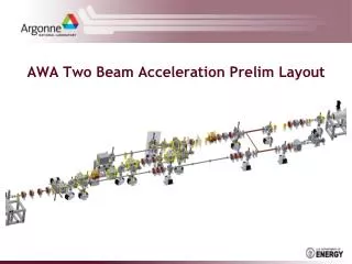
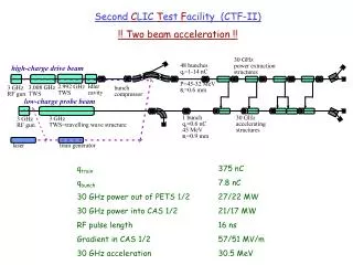
Prototype modules to be tested in CLEX - 3 modules to be tested with beam and RF - module layout compatible with CLEX requirements: • double length PETS feeding two accelerating structures • accelerating structures with all technical systems and damping • features • First module to be ready • by end of 2011 Integration of test modules in CLEX A. Solodko
PROTOTYPE Module - CLEX: Phase 3 Phase 3 foresees the installation and testing of 1 module type 0: AS equipped with WFM (5 um accuracy / few WFM in the 1st powered AS) 3.1 / Nominal power and pulse length for 1 PETS and 2 AS Recirculation 12 A and 240 ns 3.2 / No modifications on the module type 0 HW No Recirculation Current increase from 12 A to 19.2 A Pulse length reduced from 240 ns to 140 ns
PROTOTYPE Module - CLEX: Phase 4 No modifications on the module type 0 Addition of new modules - type 1 and 4 Increase of current from 19.2 A to 22 A Modification on the module type 1 (2 CLIC PETS) Needed klystrons and PC
Prototype Modules - installation in CLEX Phase 3 • Phase 3: • Existing PETS (currently under test) will be reused • It will be moved to allow for Type 0 module installation Phase 4 • Phase 4: • Instrumentation downstream the type 0 module will be removed • Installation of type 1 and 4 without displacing type 0
CONCLUSIONS • Two-beam module is part of the CLIC feasibility program • At the end of 2009 the prototype module project has been approved: 7 modules • Prototype Module project very challenging: • Non standard procurement, several iterations needed with firms • First girders in Nov 2010 for type 0 test modules in the lab, although reception at factory already started • Eucard WP 9.2 NC linac – NC accelerating cavities is part of test modules in CLEX several collaborators highly contributing • Next months will be very busy with the assembly of the first two modules: metrology and thermal cycles tests are expected to be finished before CDR
From CLIC module to CLEX module CLIC module type 0 PETS PETS (1PETS feeding 2 AS) CLEX module type 0 Double length PETS (1PETS feeding 2 AS)