Download
1 / 21
210 likes | 235 Views
This summary covers sessions on fast RF kicker design, pulsers development, and injection hardware for accelerator projects. Topics include beam coupling advantages, injection system challenges, magnet performance, and driver technologies. Insights on tapered striplines and kicker pulse waveforms are shared, highlighting implications for beam stability and injection efficiency. Case studies from various institutes offer valuable lessons on system enhancements and risk management. Attendees gain a comprehensive overview of advanced technologies and strategies for optimizing accelerator operations. Join us for cutting-edge developments in accelerator systems design and implementation.

E N D
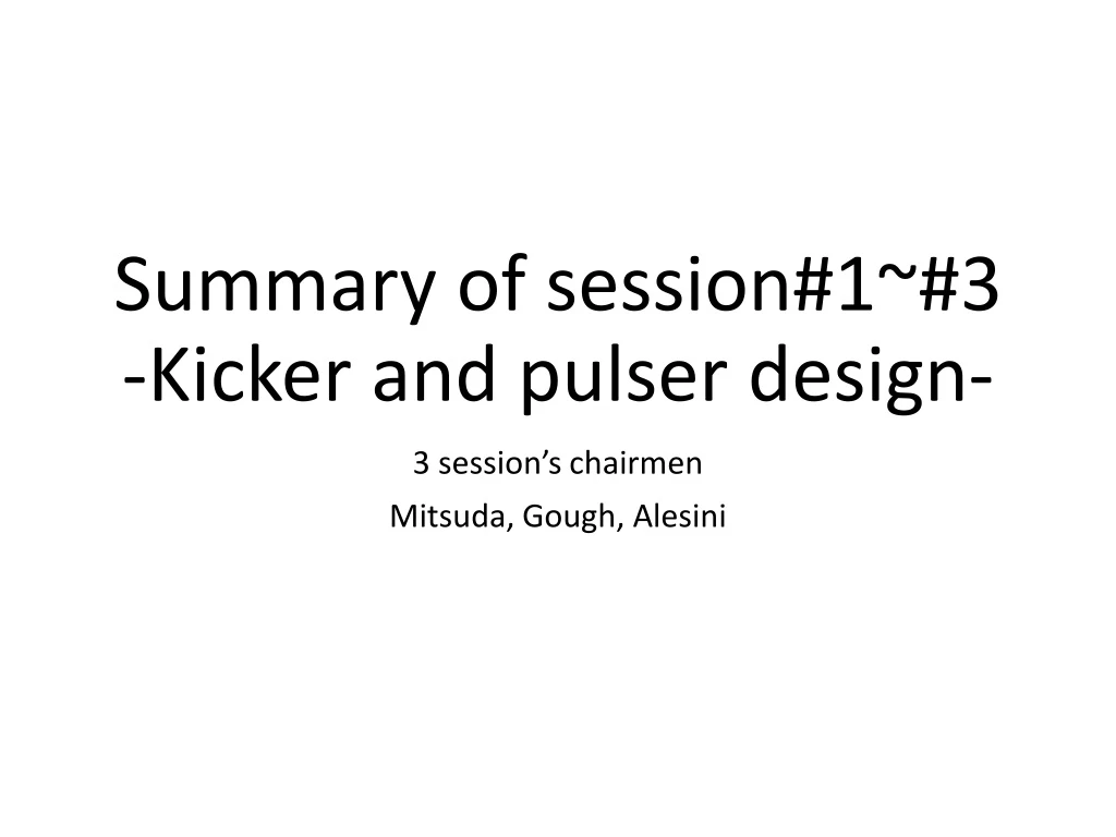
Summaryofsession#1~#3-Kicker and pulser design- 3 session’s chairmen Mitsuda, Gough, Alesini
Wehave9topicsinoursessions as follows • Fast RF Kicker Design, David Alesini • Pulsed multipole magnets for UVSOR-III and AichiSR, Yoshifumi Takashima • Development of pulsed magnets at HZB – system enhancements, Olaf Dressler • Development of ceramic chamber with integrated pulsed magnets for Spring-8 and KEK PF ,ChikaoriMitsuda • Progress on Injection hardware developments for the HEPS project, Jinhui Chen • Overview of driver technologies for nanosecond TEM kickers, Anatoly Krasnykh • Fast pulse waveforms for different injection schemes using kicker pulsers, Robert Littlewood • Development of injection elements for SLS 2.0, Christopher Gough
Fast RF kicker design David Alesini (INFN-LNF Frascati)
ADVANTAGES OF TAPERED KICKERS ON BEAM COUPLING AND TRANSFER IMPEDANCES The advantages in tapering the striplines of the kickers can be pointed out with simple electromagnetic simulations. We considered, as an example, the case of a kickers with the dimensions reported in figures. The two kickers give the same deflecting field for a given strip voltage and have the same electrical length. The longitudinal beam coupling impedance and the transfer impedance calculated by GdfidL in the two cases up to 20 GHz are reported in figures. The results show the strong reduction of the impedance and transfer impedance content when we have a tapered geometry. D. Alesini, 2° RUL Topical Workshop on Injection and Injection Systems, PSI, 1-3 April 2019
Summary for 1st talk, Alesini, DAPHNE injection kicker • The stripline kicker development for the DAPHNE ring at Frascati is copied in several other institutes. • The tapering of striplinesminimised coupled longitudinal signal and maximised homogeneity. • But to reach useful deflection with a large 50mm separation of striplines demanded at first +/-45kV then +/-25kV pulsers. • Regretably, the failure mode of these pulsers remains unknown and brings large doubt for all other institutes. In spite of using lower voltage, the striplines have been successfully re-used for combined injection plus horizontal beam stabilising. DAPHNE risks being closed down in 18 months.
Summary for 1st talk, Alesini, DAPHNE injection kicker • Taper type stripline kicker haslow beam transverse and longitudinal beam coupling impedance, important for high beam current • Beam coupling risks destroying the pulser • Feedthrough for highvoltage and 50Ω is not available → Thisisalsoimportantkeytechnology • Fast pulsed power supply’s reliability is not achieved yet. Commercial products made by FID
Summary for 2nd talk, Takashima, UVSOR and Aichi-SR • The two rings UVSOR-III and AichiSR are 30km apart and technology is shared. A pulsed multipole magnet was installed in both these two machines (Yamamoto et al, NIMA 767 2014). • The unwanted dipole field could be nulled by adding ferrite strips. The injection efficiency was low, both with the 4 dipole kicker and the pulsed multipole magnet, probably due to the injector. • At UVSOR-III, the injection efficiency was lower with the pulsed multipole. At Aichi pulsed multipole gave much lower beam displacement but spread the injected bunch due to a large on axis field. Magnet measurement showed a distorted field from a combination of proportional and derivative signals, about half from the magnet and half from the ceramic chamber. • In present operation, the 4 dipole kickers are still used in both machines.
Summary for 2nd talk, Takashima, UVSOR and Aichi-SR • Low injection efficiency issue < 30% • Its issue is same situation among KEK, UVSOR, and Aichi SR • The cause of low injection efficiency needs investigation. • Eddy current effect is observed so as to disturb the stored beam • This issue was founded in KEK and Aichi-SR • Eddy current fields come from both the ceramic coating and from the magnet body • UVSOR didn’t find the eddy current effect at that time. • So, air-core magnet is one candidate for multi-pole kicker injection scheme and the coating improvement is necessary • It seems to be difficult to find a compromise for the wall current passage and eddy current effect
‘Development of Pulsed Magnets at HZB - System Enhancements’ O. Dressler – 2nd Topical Workshop on Injection and Injection Systems,PSI Villigen, Switzerland, 1 - 3 April 2019
Mitigation by Series Connection of two Kicker Magnets Mitigation:The matching of the two pulse currents is ± 0.5 %. • Idea: • Move septum magnet to the beam axis by 1/3. • Reduce kicker pulse current from 6.8 kA to 4.5 kA. • Relaxing injection geometry. • Series connection of two kicker magnets on one pulser unit each side of septum magnet. • Maintaining only two independent pulse current shapes and timings equal. • Result: • The injection became much less sensitive to timing adjustments and jitters of the two pulsers. • The sensitivity to trigger timings decreased from ±35 ns before to about ±350 ns now. Difference
Summary for 3rd talk, Dressler, HZB activity report for pulsed kicker system • Precise diagnostics kicker power supply system for kicker fault was established. • BESSY-II uses 14bit 100MS/s DAQ to give shot-shot online plots of kicker amplitude and pulse duration. • A replacement booster septum is available because the 20uSievert/hour activation means repair of the operating septum is not permitted. • Some time ago, the 4-dipole kickers were re-cabled as two pairs to improve matching. • The imperfection for conventional 4 bump kickers was improved to increase the injection efficiency. • The drift in 1 month less than 2%. The septum was moved closer to the stored beam, reducing the required bump • The kickers were re-cabled in pairs. This gave relaxed timing and amplitude tolerances. • They have started a collaboration with Redondo et al to build a 8kV / 160A / 80ns rise / 350ns flat top / 10Hz pulser.
Question and discussion for kicker and pulser design • Do we have enough space more than 2m in future right source ring ? • Stripline type kicker needs long integrated module to increase kick angle • Both fast speed and strong kick are achieved simultaneously ? • Absolutely, are there no any impedance issues for beam wall current in stripline type kicker ? • Does not the blade disturb the beam passage in very closing gap < 10mm ? • Current type kicker example for NLK is possible to save the space issues because they can realize the kick angle even for short magnet length comparing with stripline kicker • FliP technology has a possibility to increase the coating thickness in order to increase the beam wall current passage performance without taking care of eddy current issue • Magnetic type kicker should be discussed more as a candidate?
chikaori.mitsuda@kek.jp • Strong development program at KEK with Kyocera to built ceramic chambers with four embedded longitudinal conductor. • For beam current shield they developed a system with combs of Ti depositions. • The overall project implied the development of several new technologies: • -Slender Metal Brazing TechnologySMBT • -High Current Base TechnologyHCBT • -Fine Line coating ProcessFLiP
Also quadrupole PM can be implemented • The devicehasbeeninstalled in the dump line in the PF beam transport line. 1st beam test was done in this February. The results are being verified deeply. It is going very well General comments: very promising technology for PM integration. Test results with single passage beam under elaboration. Opportunities of test in a ring to be discussed
Jinhui Chen Institute of High Energy Physics • On-axis swap-out injection based on ultra-fast kicker system is the baseline injection scheme for HEPS-SR so far. • The required pulses is <10ns above 3%. • A development program has seen the construction of a prototype striplinemodule. The prototype of 750mm-long strip-line kicker passed the acceptance testing in Mar 2018. • A total of eight 300mm stripline units are needed for injection, eight for extraction, 330urad/unit, 10mm separation. Individual tapered striplines took too much room so multiple striplines are mounted end-to-end inside a larger cylindrical vacuum chamber
The prototype of 300mm-long compact strip-line kicker R&D is ongoing. The preliminary test was finished and the expected test result was achieved. • For the pulsers, an impressive six-stage inductive adder driver with a coaxial line DSRD module has been tested. The DSRDs are from a Chinese company. Prepulsesuppression with a ferrite core module is used. At >15kV, <0.15% stability was measured General comments: impressive R&D work oriented to the new machine. Opportunities of test in a ring to be discussed
Anatoly Krasnykh SLAC National Accelerator Lab Present day switching with thyratrons or MOSFETreaches ~10 ns pulse length into 50 Ohms. For faster, these switches are needed to drive either shock wave lines or fast recovery diodes. The pioneering work for both was done in the 1960’s. The extreme conditions give strong practical constraints, for example ferrite breakdown of 10kV/cm limits rise time to ~1ns in a shock line. Diodes for high power applications are marketed as either DSRD (Drift Step Recovery Diode)(P-N junction recovery <400A/cm2, <4cm2 due to skin effect, <1ns rise time) or SOS (Silicon Opening Switch) (rapid resistance growth in low doped p-layer, >1kA/cm2 rise time >1ns), and these can be combined with various transmission line configurations. Also FID (Fast IonisationDynister) switches can be used. General comment: several possible techniques can be used and a summarizing table with main parameters can be very useful.
Rob.Littlewood@sydortechnologies.com Private company working on HV pulsers Mainlyfocused on gaussian HV pulses Goodresultsachieved Test with beam of thesedevicesisrecommended
Christopher Gough, PSI For the SLS-2 project, an implementation of the “anti-septum” idea was presented. With the small aperture vacuum chamber of a low emittance ring, most X-ray power is taken on the sector walls so lumped absorbers in the injection straight are no longer needed. The choice of pulse length for the kickers can be made taking into account the horizontal tune of the ring; either with a graphical tool or by simulating the integral kick taken over several turns. The stable pulsers of the existing ring will be re-used. A future upgrade to on-axis injection is kept as an option.