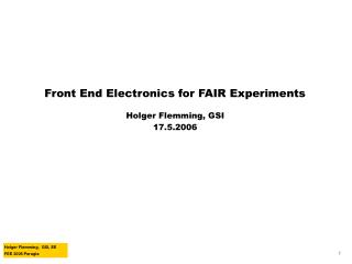
Front End Electronics for FAIR Experiments
Front End Electronics for FAIR Experiments. Holger Flemming, GSI 17.5.2006. Overview. The FAIR facility and the new experiments Requirements for FEE FEE development activities Activities at other sites Activities at GSI High resolution time measurement. GSI. SIS 100/300. CBM. Panda.

Front End Electronics for FAIR Experiments
E N D
Presentation Transcript
Front End Electronics for FAIR Experiments • Holger Flemming, GSI • 17.5.2006
Overview • The FAIR facility and the new experiments • Requirements for FEE • FEE development activities • Activities at other sites • Activities at GSI • High resolution time measurement
GSI SIS 100/300 CBM Panda HESR FAIR The FAIR Facility
The Panda Experiment • anti-Proton ANihilation at DArmstadt • Physics Topics • Charmonium spectroscopy • Search for exotic hadrons in the charm sector • Charm mesons in nuclear matter • Open charm physics • Hypernuclei • 4π detector • Anti-protons on a hydrogen pellet target
CBM - Compressed Baryonic Matter • Physics Topics • In-medium modifications of hadrons • Strangeness in matter • Indications for deconfinement at high ρB • Critical point • Fixed target heavy ion experiment • Typical parameters: • ∼107 interactions rate • ∼100 kHz channel hit rate • few MByte/s per channel • whole Detector: 1 TByte/s
Architecture given by Physics Requirements • Both Experiments: • For physics program trigger on open Charm (D0 D±) mandatory • ⇒Displaced Vertex Trigger • ⇒Track reconstruction in first level Trigger • DAQ Architecture • Self triggered FEE • Data-push architecture • Compute node farms for track reconstruction and event selection
FEE Requirements • Autonomous detecton of all hits, no trigger signal • Signal sampling and feature extraction • Absolute time stamp for each FEE device • Clock and Time distribution to each Front End channel • Shipping of all hits to the next layer • Some 100 kHz event rate per channel
FEE Developement Activities • Design of general Purpose Front End Chips to use limited man power as effective as possible • Common CMOS technology to be able to exchange functional blocks • in case of CBM: 180 µm CMOS by UMC
0,18 µm CMOS for CBM Developements • Reasons for decision: • Experiance available at the involved groups • Costs for prototyping and production affordable • From technical point of view 0,18 µm seems to be sufficiant • But: • availability in some 5 years unclear • collaboration with other institutes could be a reason to migrate • availability of special libraries ( e.g. rad hard libraries ) • We are very interessted in other institutes activities!
FEE Developement Activities (Univ. Kaiserslautern) • Developement of a widely usable Pipeline ADC IP Cell by David Muthers • Design Aims: • 10 / 12 bit resolution • Sample Frequency fS from few MS/s to 100 MS/s • Low Power Consumption ∼fS • 0,18 µm CMOS • First Testchip in 2005
3 mm 1,5 mm SRAM Pipeline Core FEE Developement Activities (Univ. Kaiserslautern) • first Testchip with configurable 10 bit / 12 bit Pipline ADC • maximum sampling frequency 75 MS/s • Power @ 75 MS/s • 10 bit mode : 30 mW • 12 bit mode : 53 mW • ENOB in 12 bit mode : 10,9 • Input Range: ±1 V differential • DNL < ±0,3 LSB • INL < ±1 LSB
1,5 mm Reference Pipeline Core 1,5 mm S&H Serializer I2C FEE Developement Activities (Univ. Kaiserslautern) • Second testchip submitted in February 2006 • careful design of clock path • Added sample & hold at input to improve high frequency performance • Serializer for Data Out • I2C-Interface for Control • Estimated performance • Sample Frequency: up to 100 MS/s • Power Consumption @ 100 MS/s: • 10 bit mode: 40 mW • 12 bit mode: 65 mW • ENOB: > 11 bit
FEE Developement Activities (Univ. Kaiserslautern) • For time stamp generation absolute clock and time distribution to FEE necessary • Idea: Using single GBit serial Link for control data uplink and clock- and time distribution • Design Challenges: • For absolute time distribution serializer and deserializer needed with clock cycle precise fixed latency ⇒ Univ. Mannheim • For clock distribution low jitter clock recovery mandatory ⇒ Univ. Kaiserslautern
FEE Developement Activities (Univ. Kaiserslautern) • First Testchips for low jitter clock recovery with on chip LC oscillators by Sitt Tontisirin • Experimantal Jitter performance: • 2,3 ps rms @ 2,5 GBit/s PRBS 27-1 • 5,9 ps rms @ 2,5 GBit/s Input-jitter 280 ps pp modulation @ 10 MHz • New Testchip submitted in February 2006 • seperate clock recoverys for deserializing and clock distribution • Expected jitter performance: ∼1 ps rms @ 2,5 Gbit/s
FEE Developement Activities at GSI • Two main activities at GSI • Low noise charge sensitive amplifier for the PANDA EMC • classical approach: Preamp / shaper close to the detector, sampling ADC and DAQ outside • Time to Digital Converter cores for a high resolution time of flight measurement at CBM • large experiance from previous time of flight systems • Evaluation of two concepts • DLL based Time to Digital Converter • Time to Ampitude converter
PANDA EMC: - PWO Crystals with APD readout - 300 pF detector capacitance - 13000 e-/MeV - Shaping time 250 ns - Dynamic range < 1 MeV to > 1 GeV - Power dissipation < 50 mW / channel FEE Developement Activities at GSI • Low noise charge sensitive amplifier for PANDA EMC • Design by Peter Wieczorek (phd student) • well known approach with folded cascode input stage • matching to PANDA EMC requirements • First Testchip ready for submission in summer this year
Chip submitted in july 2005 OTA for Vctrl Charge Pump with Loop Filter Decoupling for VDDA Delay Chain of the DLL Hit Register and Decoder Readout Circuit Decoupling for VDDD FEE Developement Activities at GSI DLL based TDC core for time of flight measurements Delay Locked Loop : Closed regulation loop Chain of N identical delay elements with adjustable delay, phase detector and charge pump. Advantage: Self Calibration to compensate temperature and process variations Intrinsic resolution of a DLL is determined by the delay of a basic cell : TBin = Tref / N HERE: 128Bins => 97.65ps @ 80MHz . N Delay Elements Reference Clock Phasedetector & Charge Pump Hit Signal Register Time 00………………..0001111111111000…..……………………….000 Hit resister stores a picture of the Hit-Signal Clock driven architecture
FEE Developement Activities at GSI • Power consumption: • VDDIO: 5,5 mA @ 3,3 V ⇒ 18,5 mW • VDDA: 6,5 mA @ 1,8 V ⇒ 11,7 mW • VDDD: 1,5 mA @ 1,8 V ⇒ 2,7 mW • Clock jitter at LastDummyOut: 6,8 ps rms • Lock range: 65 to 95 MHz • Time resolution: 31,8 ps ± 0,17 ps • DNL: + 0,37 / - 0,81 LSB • INL: + 0,66 / - 1,07 LSB
Reference Clock N Delay Elements Array of M DLL’s M x N Bins Hit Signal Register FEE Developement Activities at GSI • Next step: improving time resolutionby using shifted array of DLLs • 4 DLLs with 100 ps binning, shifted by 125 ps each • ⇒ total binning of 25 ps • design process started right now
Benefits - Time resolution not limited by delay of a digital element - Time resolution below 10 ps possible - Zero power consumption in standby mode Drawbacks - Calibration necessary - Deadtime during ramping and readout FEE Developement Activities at GSI • Digital delay chain • Distributed RC-Network • Voltage on Cout increases linear with time TDC core with a time to ampitude converter (TAC)
FEE Developement Activities at GSI • TAC-ASIC by GSI and FhG IMS in 0.8µm CMOS • Used in FOPI RPC Readout • Time resolution better than 10 ps TAC based TDC already successfully implemented
FEE Developement Activities at GSI • 2 TAC TDC Cores • SC attenuator to avoid rail to rail signals • Common clock and analog output • LVDS inputs • Some more teststructures First TAC Testchip in 180 nm 1,5 mm clock distribution TAC 1 SC attenuator 1 dual core control 3,24 mm analog output buffer SC attenuator 2 TAC 2
Chip submitted in april 2006 FEE Developement Activities at GSI Simulation of First Testchip
Summary and Outlook • New heavy ion and anti proton facility FAIR will arise at GSI • Two large experimental setups PANDA and CBM with similar requirements • R&D on FAIR front end electronics has just started • First examples for different developments have been presented • Other projects not mentioned • MAPS for CBM vertex detector • Silicon strip readout • …