Download
1 / 27
270 likes | 288 Views
Explore the innovative front-end electronics upgrade in the HADES experiment focusing on Resistive Plate Chamber (RPC) technology. The project involves replacing the TOFino detector with an RPC wall for improved time resolution and detection capabilities. Learn about the design considerations, RPC cells, signals, electronic chain, and notable improvements. Discover the objectives, subdetectors, and advancements in the HADES experiment for studying vector meson properties in nuclear matter. Presented at the 12th Workshop on Electronics for LHC and Future Experiments in Valencia, this work highlights the critical role of electronics in modern research experiments.

E N D
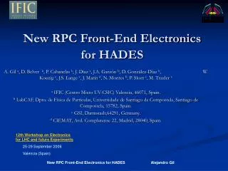
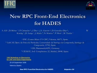
New RPC Front-End Electronics for HADES A. Gil a, D. Belver b, P. Cabanelas b, J. Díaz a, J.A. Garzón b, D. González-Díaz b, W. Koenig c, J.S. Lange c, J. Marín d, N. Montes b, P. Skott c, M. Traxler c a IFIC (Centro Mixto UV-CSIC) Valencia, 46071, Spain. b LabCAF, Dpto. de Física de Partículas, Universidade de Santiago de Compostela, Santiago de Compostela, 15782, Spain. c GSI, Darmstadt,64291, Germany. d CIEMAT, Avd. Complutense 22, Madrid, 28040, Spain. 12th Workshop on Electronics for LHC and future Experiments 25-29 September 2006 Valencia (Spain)
OUTLINE • HADES EXPERIMENT • RESISTIVE PLATE CHAMBER (RPC) WALL • RPC CELLS • RPC SIGNALS • ELECTRONIC CHAIN • FRONT-END ELECTRONICS • RESULTS • IMPROVEMENTS • SUMMARY
HADES EXPERIMENT HADES is located at the SIS accelerator of GSI, Darmstadt (Germany) GSI FAIR HADES
HADES EXPERIMENT High Acceptance DiElectonSpectrometer • Detection of electron-positron pairs produced in relativistic hadron-nucleus and nucleus-nucleus collisions with the goal of studying vector meson properties in nuclear matter, both normal and hot and compressed. • Consists of several subdetectors providing tracking, triggering, particle identification and momentum reconstruction capabilities RPC detector
HADES EXPERIMENT Objective of the project: Upgrade of HADES replacing the low angle TOFino detector for the an RPC wall TOF: Time of Flight detector (100ps time resolution) TOFino: Low angle Time of Flight detector (350ps time resolution) RPC wall TOFino (cross section of HADES)
RPC wall • The RPC wall is distributed in 6 sectors, covering an active area of 7 squared-meters. (View from inside)
RPC wall RPC wall contains 1024 double-sided readout detectors (2048 channels) • 80 times larger granularity • Time resolutions of 70 ps • Rates up to 700 Hz/cm2 • collisions from C-C to Au-Au Double layer acceptance close to 100%
RPC cells RPC Gas Box & cells(LIP-Coimbra,P. Fonte et al.) • CHEAP MATERIALS: • Aluminium • Glass • SHIELDED CELLS: • Crosstalk < 1% • GAS MIXTURE: • Freon (85%) • SF6 (15%) • Isobutane (5%)
RPC signal • Rise time ~500ps • 5ns width • Amplitudes up to 200mV • Oscillations due to impedance mismatch between the detector (20Ω) and the electronics (50Ω) 100mV 100ns
FEE design considerations • A large bandwidth to deal with short rise times of RPC pulses (about 500ps rise time and 5ns width). • Low electronic jitter and noise for good time resolutions • Charge measurement for correction • Output signal for the trigger logic of HADES. Rate < 1kHz/cm2 RPC area x100cm2 =100kHz X31 channels = 3.1 MHz firing • Size restrictions two boards DB and MB • Built with commercially available components • Moderate power consumption to reduce heat. Detector active area Front End set up on the RPC sector
DAUGHTERBOARD • Generates a time-window signal which contains information about the: • Arrival time of the RPC signal (for TOF measurement) • Charge of the RPC signal • 6 Layer board • 4 channels/board • Micro Lemo inputs • Hi-freq Samtec connector 4 2 4.5cm 1 2 3 4 5cm
R Comparator Trigger Out. Σ4ch. Amplifier 2k2 MAX9601-2ch 500ps Propagation Delay In BFT92 Wideband PNP Transistor C Latch enable 4 ch. out GALI-S66 Monolithic (20dB, 2GHz) ToF-Threshold PECL- LVDS C MAX9601-2ch SN65LVDT100 OPA690 Wideband Op. Amplifier C SAMTEC 16 diff. pins ToT-Threshold Integrator DAUGHTERBOARD Amplifier stage → GALI-S66 Discriminator stage: - Dual MAX 9601 comparator with histeresis and latch enable (2 comparators/channel). PECL-LVDS TI SN65LVDT100 converter. BFT92 transistor for multiplicity trigger.
RPC signal ToF xG RPC signal ƒ ToT Voltage (50mV/div) Integrated signal RC integrator 2ns (to avoid tail) RPC arrival time ToT Amplified RPC signal Output signal width~charge Time (20ns/div)
MOTHERBOARD • Main tasks: • Supply stable voltage to the Daughterboard +5V,-5V,+3.3V • Conentrates the time-window signals from 8 Daughterboard to 1 connector (then twisted pair cable to the TDC board). • Combines the 32 trigger signals coming out from the Daughterboard to provide only 1 multiplicity signal. • Allocates DACs for the threshold voltages of the comparators on the Daugherboard • Minor tasks: Test signals multiplexing, LVDS repeaters,interface for DACs programming, etc 6cm 40cm
MOTHERBOARD 1) Supply stable voltage to the Daughterboard • Ripple filtering DC-DC converter Motherboard +5V -5V +3.3V Different decades C Ferrite bead Uses the plugged vias technique to: reduce ESR and ESL layout effects in filter capacitors and PCB dimensions
MOTHERBOARD 2)Conentrates the time-window signals from 8 Daughterboard to 1 connector (then twisted pair cable to the TDC board). Interface: Low Voltage Differential Signaling (LVDS) Also used for: • DACs programming • Test signals delivery Advantages: • Low power consumption • High noise inmunity Diferential impedance matching lines and termination resistors (100Ω) to reduce signal reflections/distorsions
MOTHERBOARD 3) Combines the 32 trigger signals coming out from the Daughterboard to provide only 1 multiplicity signal. Low level trigger: • Two-stage circuit • Summing OPAMs • OPA690 • High slew rate • High output swing • -100mV contribution per channel
TDC board DOCSCLK Motherboard DAC1 DAC2 DAC8 MOTHERBOARD 4) Allocates DACs for the threshold voltages of the comparators on the Daugherboard • DACs Thresholds • 8 DACs/Motherboard • 8 Channels/DAC • LTC2620 • 12 bits resolution • Low noise • Low power consumption • Daisy-chained • SPI programming
ELECTRONIC CHAIN Daughterboard Motherboard Daughterboard 4 channels Motherboard8 Daughterboards Time Readout Board (TRB) 4 Motherboards DC-DC converter 2 MB. RPC TRB DC-DC converter
TRB Time Readout Board: • Custom TDC-Readout-Board • Muli-purpose 128-channel • Requires 1 channel for timing • Based on the HPTDC ASIC developed at CERN GSI (M. Traxler et al.)
DC-DC converter • Input: +48V • Output: +5V,-5V&+3.3V • 2xDATEL 5V (12A)modules. 100mVpp ripple@20MHz • POLA 3.3V 40mVpp ripple @20MHz • Extra filtering at the input and output: 25mVpp ripple @20MHz GSI (M. Traxler et al.)
RESULTS Full chain: Detector+FEE+TRB ToFThr=15mV ToTThr=-20mV <0.5W/channel Crosstalk<1% Jitter: 50ps Output width vs charge correlation for gamma illumination using 60Co source Beam results 1GeV C-C collisions
IMPROVEMENTS • DAUGHTERBOARD • Only one comparator • 30% less consumption per channel • Expected to improve the output width vs. charge correlation Charge comparator removed
IMPROVEMENTS • MOTHERBOARD • Ripple filtering improvement • DACs readback to check that the data has correctly received • Trigger system will be redesigned because the actual OPAMs produce big overshootlower slow rate
SUMMARY • The actual FEE fits HADES requirements. 2 Motherboards with 64 channels has been evaluated under: - pulse generator - gamma source - under beam • Still some improvements commented have to be done, as well as some long term stability tests. Noise/crosstalk measurements should be done in more detail. • Next step will be to cover 2 sectors of the actual detector in February 2007
Acknowledgments • Hector Alvarez (LabCAF-Universidad de S. Compostela) • Alberto Blanco (LIP-Coimbra) • Paulo Fonte (LIP-Coimbra) • Gerhard May (GSI) • Martin Zapata (LabCAF-Universidad de S. Compostela)