Download
1 / 17
170 likes | 772 Views
DC Fan Speed Control PWM Signal Introduction. Wayne_Chen ADDA RD Chief Engineer Wayne@adda.com.tw 886-8-755-0579 ext:326. Speed Control Fan Configuration (old version) What is PWM Signal ? PWM Control Methods Introduction PWM Fan Specification PWM Fan Sample Q & A. Topical:.

E N D
DC Fan Speed Control PWM Signal Introduction Wayne_Chen ADDA RD Chief Engineer Wayne@adda.com.tw 886-8-755-0579 ext:326
Speed Control Fan Configuration (old version) What is PWM Signal ? PWM Control Methods Introduction PWM Fan Specification PWM Fan Sample Q & A Topical:
1. Speed Control Fan Structure(old version) 1-1. Use ON/OFF control by Transistor • Advantage: • Easy design and control method • Price cheaper. • Disadvantage : • Power Dissipation is a design issue. • Not use friendly.
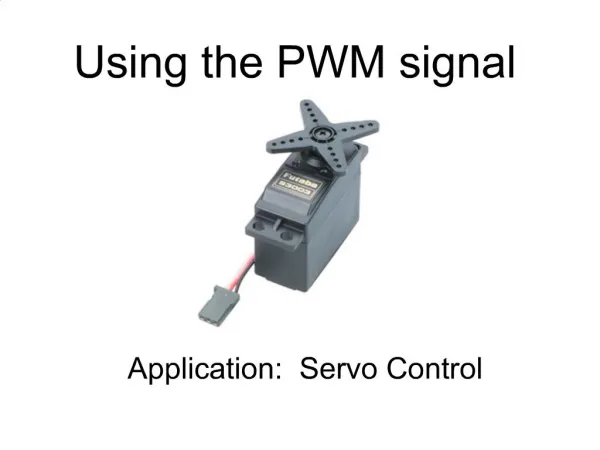
PWM(Pulse Width Modulation): It’s a fixed frequency and pulse modulated for fan speed control. Whenever change the duty cycle, the fan speed will be changed by system requirement. 2. What is PWM Signal ? • The Purpose are : 1. The power dissipation will be saving. 2. And the working time will be increasing if the battery could not be charged outside. (especially NB system) Figure : PWM Control Signal
3. PWM control Methods introduction 3-1Speed Control Fan Structure (old version) • Use ON/OFF control by Transistor • Advantage: • Easy design and control method • Price cheaper. • Disadvantage: • Poor Reliability ( Transistor are On/OFF continuously) • Error judgment of tachometer signal.
Actual Tachometer Signal Waveform PWM input signal Error judgment of tachometer signal
3-2. Regulator Control Fan Configuration (Current version For Notebook <Three Wires>) • Advantage: • The better Reliability • RPM Stable • Power efficiency saving. • Disadvantage: • Cost expensive. • Control Circuit Complex
Actual Tachometer Signal Waveform PWM input signal tachometer signal ( normality)
3-3. Control PWM Fan Configuration<Four Wires> Fan System PWM control Configuration
Type A 3-4. Next Generation Version PWM Control Fan: Type A
3-5. PWM Control Fan: Type B Type B
PWM Operating Frequency : 25kHz ± 5kHz Maximum Input Low Voltage (VIL-MAX) = 0.8V Minimum Input High Voltage (VIH-MIN) = 2.0V High Input Impedance (10K ohms at least ) (Consider Fan-In Issue,Driver Capability) 4-1. PWM Input Signal Specification (from system)
Operation Voltage : 5V or 12V ± 10% Function: Locked Protection and Auto-restart Apply the Open Collector or Open Drain Tachometer Output Signal Low Speed setting with 0~17% (or 20%) on Same PRM level (Type B) 4-2. PWM Fan Specification
5-1. Type A( For NB fan suggestion) 5. PWM Fan sample Fan Stop Duty Cycle Fan Start_up Duty Cycle
5. PWM Fan sample 5-2. Type A( All kind of fan could be used.) Fan Stop Duty Cycle Fan Start_up Duty Cycle
It’s same duty cycle curve for fan start_up and stop. 5. PWM Fan sample 5-3. Type B(For Desktops fan suggestion)