Download
1 / 3
30 likes | 49 Views
Learn the impact of mask misalignment in digital and analog circuits due to variations in X and Y directions. Discover modeling suggestions for mitigating mismatches and timing errors caused by mask registration problems.

E N D
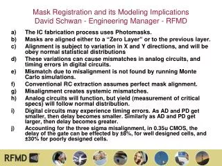
Mask Registration and its Modeling ImplicationsDavid Schwan - Engineering Manager - RFMD • The IC fabrication process uses Photomasks. • Masks are aligned either to a “Zero Layer” or to the previous layer. • Alignment is subject to variation in X and Y directions, and will be obey normal statistical distributions • These variations can cause mismatches in analog circuits, and timing errors in digital circuits. • Mismatch due to misalignment is not found by running Monte Carlo simulations. • Conventional RC extraction assumes perfect mask alignment. • Misalignment creates systemic mismatches. • Analog circuits will function, but yield (measurement of critical specs) will follow normal distribution. • Digital circuits may experience timing errors. As AD and PD get smaller, then delay becomes smaller. Similarly as AD and PD get larger, then delay becomes greater. • Accounting for the three sigma misalignment, in 0.35u CMOS, the delay of the gate can be effected by ±8%, for well designed cells, and ±30% for poorly designed cells.
Poly Alignment Left Drain -> AD, PD are larger Right Drain -> AD, PD are smaller Left Source -> AS, PS are smaller Right Source -> AS, PS are larger Mirrored Devices are not Matched
Suggestions for Implementation • Circuit designers are in need of a way to predict whether their circuit has sensitivities to mask registration. • Building sensitive information (alignment data) into simulation model allows user to leverage this information, and gain insight into their circuit. • Value in microns (or nm) is typically not released, this is considered proprietary information • Structures can be built to measure amount of misalignment; requires special knowledge on the part of the designer. • Add modeling for this to the statistical model. Any change to AD/PD/NRD need to be mirrored by an opposite change to AS/PS/NRS. Example: AD=AS=1um2 PD=PS=3um With example shift (0.1um): AD=0.8um2 AS=1.2um2 PD=2.8um PS=3.2um NRD and NRS need to change accordingly.